5.2 Feeder setting
Select one feeder, tick “Apply”, then its related info can be edited such as feeder exchange, feeder, nozzle, IC tray feeder etc.
The setting sequence for them should be: Feeder (or IC tray feeder)→ Feeder basic information→ Nozzle.
P. S.: 1) For feeders 1-66, the IC tray feeder is in disabled condition. 2) Feeder exchange depends on application condition,
if the tape reel was installed on wrong feeder, you can directly use feeder exchange to solve it.
(
1
)
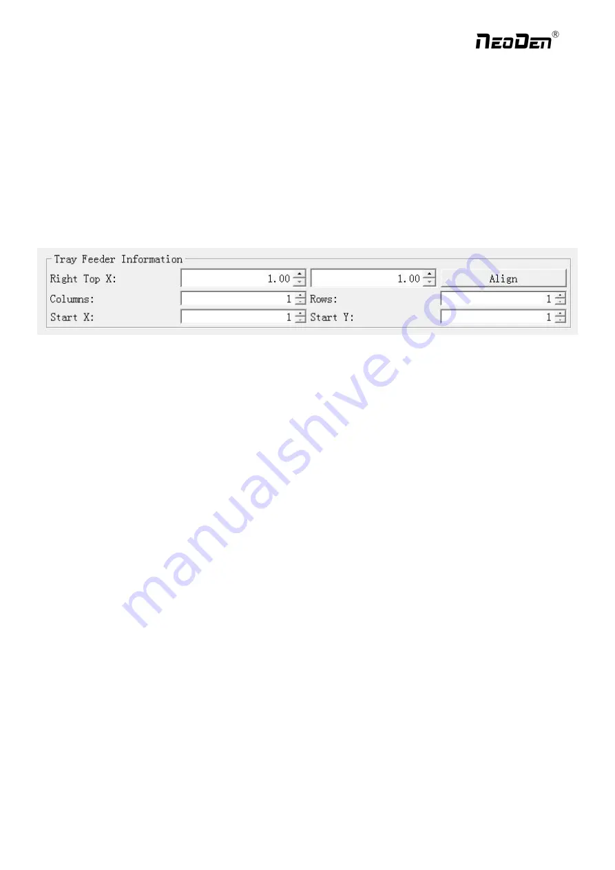
IC tray feeder info
It is used to set tray package component’s pick position.
Right top XY: it refers to align the farthest component on the tray (generally take the component at right top as the
final one on the tray, and take the component at left bottom position as the first one)
X qty: it refers to how many components in X direction
Y qty: it refers to how many components in Y direction
Start X, Start Y: It refers to the first IC in X/Y direction if the tray is in full package; If some ICs have been used whic
h cause the tray is not full, you can directly set the exact position as actual situation, start X will be the location of its a
ctual column and start Y will be its actual location of row.
(
2
)
Feeder basic info
Skip: once selected, all components in this feeder will be skipped.
Feeder exchange: this function can be used if any reel tape was installed at wrong or inappropriate position. Select
the feeder/ IC tray feeder you need to exchange, then the related feeder info will be synchronized to the swapped
feeder/ IC tray feeder.
Pick XY: Align the first component position in the feeder as fig.4.2.2, which is Mark camera align the component
central position, then click ”save and back”, the well-saved position’s X/Y coordinates will be automatically show up
as fig. 4.2.1 (P.S.: pick position can be set one by one or be set by the scale setting, scale setting is more convenient).
27
Zhejiang
NeoDen Technology Co.,Ltd.


