14
5.1. UV System
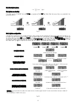
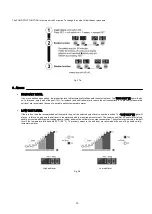
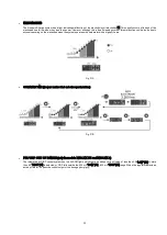
The UV system automatically powers the lamp once it is connected by the switch located on rear side of the control panel of the unit (see 4.3). After
a few seconds, once the system detects that the lamp is ignited, the led "lamp" [19] on the control panel of the unit will stay on. The main screen [18]
will show at all times the number of hours of lamp operation.
Hours of operation
By pressing "PROG" [20], the main screen [18] will show the number of "ignitions" of the lamp.
5.1.1. Alarms
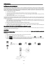
Whenever the system detects a problem in the power supply circuit of the UV lamp, the alarm led [21] lights on the control panel of the unit.
LAMP
If the lamp does not start at the preset time, the main display [18] will show the message "NO RADIATION".
OPTIONAL EXTERNAL FLOW DETECTOR (FLOW SWITCH)
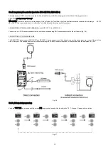
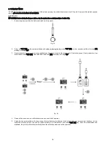
If during the configuration process of the system a flow detector (flow switch) is connected to the [CN6] input at the system control board
(by default, this input is provided bridged), the system automatically disconnects the lamp flashing the message "noFLO" in the system
information display [18].
The system automatically restarts once the water flow through the flow switch is restored.
Remember
Whenever the lamp is replaced you must reset the hour meter of the system. To do so, switch on the UV system with
the main switch keeping pressed the "PROG" key [20] on the control panel until you see the message "RESET" on the
main screen [18].
Summary of Contents for NEO-12
Page 2: ......
Page 5: ...3 3 DATASHEET...
Page 6: ...4...
Page 7: ...5 Fig 1...
Page 9: ...7 4 3 Electrical connections...
Page 10: ...8...
Page 14: ...12 4 7 Connection PoolStation...
Page 18: ...16 Fig 23 System programming flow sheet...
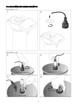
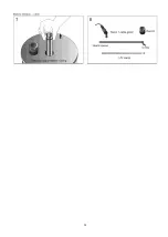
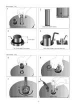
Page 29: ...27 7 1 3 REPLACEMENT AND CLEANING THE LAMP U V...
Page 30: ...28...
Page 31: ...29...


