background image

SI 72

Disconnect the mains supply before performing 
any maintenance. 

The user must not attempt to service the 
appliance beyond that described in this operator 
manual. All other servicing must be referred to 
qualified service personnel only. For service 
please contact your authorized distributor.

The machine must be kept in proper condition by regularly 
removing dust, paper remains, etc. Clean the sealing table 
and rubber rollers when dirty with glue. This can be donde by 
using a slightly wetted cloth soaked in warm water. 

8. MAINTENANCE

8.1 Servicing

Fig. 56

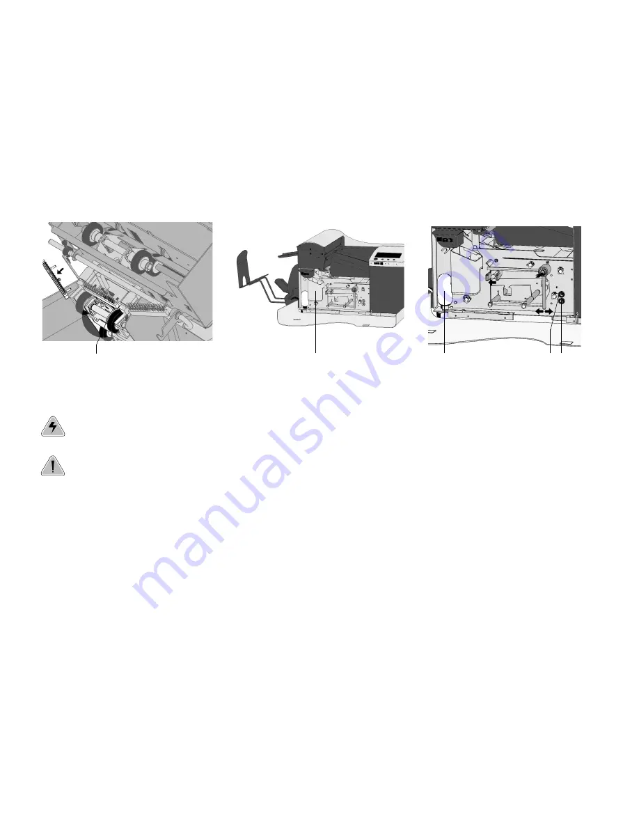
8.3 Cleaning the brushes

Clean the brushes when dirty or saturated with glue. An
extra set of brushes is provided. The best procedure is to
always soak one set of brushes and use the other set. In
that way there is always a clean set of brushes ready for
usage.

To replace the brushes the loc must be lifted. The brushes
can be removed one by one by pulling them straight off the
brush holder (see fig. 56). When replacing the brushes,
align the studs on each brush with the respective holes in
the brush holder.

It is also possible to remove the brush holder completely.
Pull tongue A (fig. 56) down and the brush holder out of
the loc.
To replace the brush holder, slide the tongue on the holder
into the loc and press downwards and inwards to click in.

The brushes should be cleaned once a week.

8.4 Cleaning the moistening felt

Clean the moistening felt and water tray when dirty or
saturated with glue. To remove the water tray the side 

Fig. 57

cover must be opened. Then pull the locking handle A (fig.
57) of the loc up and lift the loc.

Pull out the water tray B and clean it under running water.
Replace the water tray, lower the loc until it clicks and close
the side cover.

8.5 Cleaning the fold rollers

To  clean the fold rollers in the PowerFold

TM

open the

PowerFold

TM

cover (see page 25).

Clean the fold rollers in the PowerFold

TM

regularly  with a

dry duster or a cleaner (don’t use chemical products!).

8.6 Cleaning the sensors

When the display shows a message like “Track sensor
dusty”, the sensors on the envelope or document path must
be cleaned. The screen on the display indicates which
sensor(s) must be cleaned.

The sensors can be cleaned by using the bellow A  
(fig. 58) located behind the side cover.

To  clean the sensors, put the bellow in hole B (fig. 58).
Squeeze a few times firmly to blow away the dust from the
sensors. Repeat this procedure for hole C (fig. 58).

Fig. 58

8.2 General cleaning

B

A

A

C

B

31/33

SI 72

Summary of Contents for SI 72

Page 1: ...nd then seals and stacks the envelopes Automatic monitoring ensures the correct number of inserts per envelope The machine is equipped with a variety of special features as document thickness detection programmable jobs Load N GoTM FlexFeedTM double feed control hopper swap multifeed daily mail IntelliDeckTM and PowerFoldTM ...

Page 2: ...controls 4 2 3 Display buttons 5 3 PREPARATIONS 5 3 1 Moistening the brushes 5 4 OPERATING THE MACHINE 5 4 1 Switching on 5 4 2 The main menu 6 4 3 Job info screen 6 4 4 Other job menu 7 4 5 Adjustment of the document hopper 7 4 5 1 Document separation 7 4 5 2 Side guides 7 4 5 3 Filling the document hopper 8 4 6 Adjustment of the document stoppers 8 4 7 Feeding documents 9 4 8 Adjustment of the e...

Page 3: ... this way the system does not need to stop The correct sets will be transported to the PowerFoldTM part PowerFoldTM see 4 The PowerFoldTM part folds the documents The following fold types are possible no fold single fold letter fold zig zag fold double parallel fold Inserter see 5 After folding the documents are transported to the inserter unit where the documents are inserted into a waiting envel...

Page 4: ...C loc D locking handle loc E control panel F vertical transport opened G vertical transport hand grip H document feed tray I collator arm J collator area K PowerFoldTM cover opened L locking handle PowerFoldTM M power inlet power switch and fuse N handle for clearing stoppages O handle for clearing stoppages P water tray Q bellow R side cover opened Fig 3 Fig 4 A B C D E G F H I J L M N O P Q R K ...

Page 5: ...a special section is available in the water tray In that way there is always one set ready for usage To fill the water tray lift the locking handle B fig 6 of the loc Then pull up the loc into the vertical position Open the side cover R fig 3 on page 4 and fill the water tray to the max level Before moving the machine the watertray must be empty Fig 6 4 OPERATING THE MACHINE 4 1 Switching on The m...

Page 6: ... main menu 2 key 6 Fig 8 The main menu 2 as shown in fig 9 shows 5 different functions job information key 1 display contrast lighter key 2 display contrast darker key 3 go to the job menu key 4 only for authorized personnel back to the main menu 1 key 6 Fig 9 4 3 Job info screen When key 1 is pressed in a menu the job info screen will be displayed Press key 6 to go back to the main menu 1 The job...

Page 7: ...ually as follows push the knob A fig 12 forward until it clicks open the left side guide B fig 12 by turning it downwards place a document on the feeding tray and slide it about 60 mm 2 4 inch into the machine turn the knob A counter clockwise if the separation is set to narrow push the document between the rollers turn the knob A clockwise to get more resistance or counter clockwise to lower the ...

Page 8: ...nts depending on the type of documents and the type of fold as shown in 4 7 Feeding documents page 9 Fig 15 4 6 Adjustment of the document stoppers The position of the document stoppers can be adjusted according to the longest document used the document size is programmed in jobs Initially the document stoppers are set to position B In this position a wide variety of documents can be handled and a...

Page 9: ...eading Address carrier in top linked pair feeders Face up and leading Address carrier in top feeder Face up and leading Address carrier in top feeder Face up and leading zig zag fold Address carrier in bottom feeder Face down and trailing Address carrier in bottom linked pair feeders Face down and trailing Address carrier in bottom feeder Face down and trailing Address carrier in top feeder Face d...

Page 10: ... Fan the envelopes a bit see fig 18 and place the envelopes in the hopper with the flap down and trailing on the envelope support B fig 17 The bottom envelope must enter the separator first Adjust the side guides C fig 17 by turning the thumbwheel A fig 17 to provide enough space to move freely Too much play causes skewing 4 8 3 Envelope support Adjust the envelope support B fig 17 so that the fla...

Page 11: ...er of the loc and pull the loc into the vertical position The flap folding line must be positioned under the green indicator A fig 22 If necessary adjust the flap folding line position by pressing key 4 or 5 in the test run menu Each key stroke stops the next envelope 0 5 mm 0 02 Fig 21 inch to the right earlier or to the left later Check the settings by pressing key 1 again 4 11 Envelope insert f...

Page 12: ...ey 6 Fig 24 4 14 Load N GoTM menu When the system is equipped with the Load N GoTM function this will be displayed in the main menu 1 After pressing key 5 in the main menu 1 the Load N GoTM menu is displayed fig 25 The Load N GoTM function can be used for creating simple jobs The machine automatically recognizes the document size envelope size and necessary fold settings The adjustment of the enve...

Page 13: ...opper swap the machine switches automatically to the upper hopper when the lower hopper is empty and vice versa multifeed more sheets are fed from the same hopper into the envelope The usage of the Load N GoTM function is not possible in the no envelopes mode or with usage of envelopes with open flap The Load N GoTM job can not be saved When the machine is switched off the settings will be lost Fi...

Page 14: ...lope support page 10 receiving tray page 10 envelope sealing page 11 Mechanical adjustments Job info page 6 Adjust contrast page 6 Enter job menu page 6 To main menu 1 Job info page 6 Select higher job number page 7 Select lower job number page 7 Confirm settings Key Feed one evelope page 11 Insert one document page 11 Stop position to the right page 11 Stop position to the left page 11 Confirm se...

Page 15: ... job key 3 copy a job key 4 delete a job key 5 exit and go back to the main menu 2 key 6 The escape key will get you back to the previous menu Fig 30 5 2 Create job menu After pressing key 2 in the job menu the display will show the create job menu as shown in fig 31 If all jobs are programmed the display shows No more free jobs The create job menu shows the following functions choose a higher fre...

Page 16: ...copy job menu as shown in fig 33 The copy job menu shows the following functions job information key 1 choose a higher job number to copy from key 2 choose a lower job number to copy from key 3 choose a higher job number to copy to key 4 choose a lower job number to copy to key 5 copy the job with OK key 6 which will get you to the job menu If all jobs are programmed the display shows No more free...

Page 17: ...nvelope settings menu When the envelope settings menu is selected and confirmed in the job settings menu the display shows the screen as shown in fig 36 In this menu the following choices are available by pressing key 1 1 Envelope with closed flap 2 Envelope with open flap 3 No envelopes 6 1 1 Envelope with closed flap When envelope with closed flap is selected the display shows the screen as show...

Page 18: ...n in fig 38 The following choices are available go to the envelope with closed flap screen key 1 confirm the settings by pressing OK key 6 which will get you back to the job settings menu Fig 38 6 2 Document settings menu When the document settings menu is selected and confirmed key 6 in the job settings menu the display shows the screen as shown in fig 39 The following choices are available by pr...

Page 19: ...e of the documents in the selected feeder key 5 confirm the settings by pressing key 6 which will get you back to the job settings menu The document size can be set between 90 mm 3 54 inch and 356 mm 14 inch in steps of 1 mm 0 04 inch The default document size setting of a new job is 297 mm 11 7 inch The position of the document stoppers is set by service personnel according to the document sizes ...

Page 20: ...fold 3 Letter fold 4 Zig zag fold 6 3 1 No fold When no fold is selected the display shows the screen as shown in fig 43 The following choices are available go to the single fold menu key 1 select settings by pressing OK key 6 which will get you back to the job settings menu Fig 43 6 3 2 Single fold When single fold is selected the display shows the screen as shown in fig 44 The following choices ...

Page 21: ...then the length of the longest document used Fig 45 6 3 4 Zig zag fold When zig zag fold is selected the display shows the screen as shown in fig 46 The following choices are available go to the no fold menu key 1 increase the position of the first fold to the right key 2 decrease the position of the first fold to the left key 3 increase the position of the second fold to the right key 4 decrease ...

Page 22: ...ey 5 in the double document detection settings menu the display shows the screen as shown in fig 48 The following choices are available set the position of the detection area earlier key 3 set the position of the detection area later key 4 confirm the settings by pressing OK key 6 which will get you back to the double document detection menu Fig 48 6 5 Job name menu After pressing key 5 in the job...

Page 23: ...ea see page 22 No envelopes see page 18 Hopper swap see page 19 Letter fold see page 21 Daily mail see page 20 Zig zag fold see page 21 Select settings menu page 17 Edit selected settings menu page 17 Enter job name menu page 22 Save job settings and return to the job menu page 17 Job information Select job to create edit page 15 Copy job page 16 Delete job page 16 menu page 17 Exit job menu and g...

Page 24: ...nical problem the display shows the message in figure 51 This error cannot be solved by operating personnel and assistance of the service support is needed First switch the inserter off and on again to verify machine operation When the error still occurs write down the error code and contact your service organisation Warning screen The display shows a warning screen with the message Cover open and...

Page 25: ...tion remove all material from the insert area lower the loc and close the side cover Reset the error after solving the problem with key 6 PowerFoldTM When a stoppage occurs in the PowerFoldTM remove the documents from the PowerFoldTM as follows push the lower end of the locking handle B to open the PowerFoldTM cover A fig 54 remove the documents from the PowerFoldTM close the PowerFoldTM cover Res...

Page 26: ...ument stoppage Remove documents Page 25 Inserting failure 1 18 Envelope stoppage Remove envelope Page 25 Flap sensor covered 1 19 Envelope stoppage Remove envelope Page 25 Envelope lost 1 20 Thickness not measured Remove documents Page 25 Wrong measurement area 1 21 Envelope stoppage Remove envelope Page 25 Wrong envelope size 1 22 Document stoppage Remove envelope Page 25 Seal switch active 1 24 ...

Page 27: ...ent stoppage Remove documents Page 25 Stoppage at collator 3 11 Document stoppage Remove documents Page 25 Stoppage at collator 3 12 Document stoppage Remove envelope Page 25 Stoppage at divert 3 13 System not ready Remove all documents Page 25 Documents in system 3 20 Empty feeder Load documents Page 8 3 21 Feeding failure Remove documents Page 25 Document too thick 4 5 6 or 7 10 Feeding failure ...

Page 28: ...he hopper Check and replace if needed Envelope stop skewed Side guides of the envelope hopper are set too wide Check side guides and adjust if needed 10 Envelopes are fed irregularly Hopper almost empty Refill hopper 10 Separation set too narrow Check separation settings adjust if needed 10 Side guides set too narrow Check side guides and adjust if needed 10 Envelope support not positioned correct...

Page 29: ...rushes clean if needed 30 Moistening felt dry Check the moistening felt refill water tray if needed 5 Moistening felt dirty Check the moistening felt clean if needed 30 Moistening brushes inactive Activate the moistening brushes 11 Envelope not always Inserted document too big Check fold settings adjust if needed 20 ejected from sealer Document not inserted deep enough Check adjustment of envelope...

Page 30: ...p This means that two feeders can be linked as pairs When the first feeder is empty the system switches to the other feeder Meanwhile the other empty feeder can be refilled without stopping Multifeed It s also possible to feed multiple documents from one feeder In this way more documents of the same can be fed from one station for example an original and a copy of a document Conveyer stacker At th...

Page 31: ...tongue A fig 56 down and the brush holder out of the loc To replace the brush holder slide the tongue on the holder into the loc and press downwards and inwards to click in The brushes should be cleaned once a week 8 4 Cleaning the moistening felt Clean the moistening felt and water tray when dirty or saturated with glue To remove the water tray the side Fig 57 cover must be opened Then pull the l...

Page 32: ...s to machines as from machine number 99CF 5001 or higher Machine specifications Model SI 72 Type inserter system for medium office use Overall dimensions 2 station system 4 station system height 570 mm 22 4 inch 743 mm 29 3 inch width 420 mm 16 5 inch length 1590 mm 62 6 inch 2 station system 4 station system Weight 88 5 kg 195 lbs 96 2 kg 212 lbs Noise level 70 dBA following DIN 45635 part 19 The...

Page 33: ...rective 89 336 EEC modified by the directives 92 31 EEC and 93 68 EEC It is forbidden to put the product into use before the equipment to which it is connected declared to be in accordance with the stipulations of the Machine Directive 33 33 SI 72 Remarks The specification of the paper handling equipment is often wider than that of the envelopes and documents handled The condition of material hand...

Reviews: