N27 EVK User Guide
Chapter 2 About N27 EVB
Copyright © Neoway Technology Co., Ltd
3
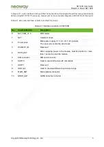
In Figure 2-1, each interface and keys of N27 is marked in red rectangles. Read this user guide carefully
before using N27 EVB. If necessary, please refer to the schematic diagram and PCB file of the board.
Table 2-1 lists each interface or button and their functions.
Table 2-1
Interfaces and button of N27 EVB
No.
Interface/Button
Description
0
N27_EVB_V1.0
EVB model
1
N27
Cellular module
2
Power pads
Main power supply, 3.1V to 4.3V, 3.6V typically
The input current shall be 2A at least.
3
WAKEUP_IN
Reserved
4
PWR_KEY
After supplying power to the module, hold this button for more
than 1 second to start the module.
5
SIM connector
SIM card connector
6
UART0
Used to send and receive AT commands
7
UART1
Reserved
8
USB port
Used to download firmware and capture logs
9
MAIN_ANT
Main antenna connector
10
GNSS_ANT
GNSS antenna connector


