background image


N27 EVK User Guide 

Chapter  3  Power  and  Connection 


Copyright © Neoway Technology Co., Ltd 


Power and Connection 

Power is supplied for the N27 EVB only through external power cables. The N27 EVK provides one 
M5X0-PWR cable and one Micro-USB cable for data communication. 

3.1 

Power Supply 

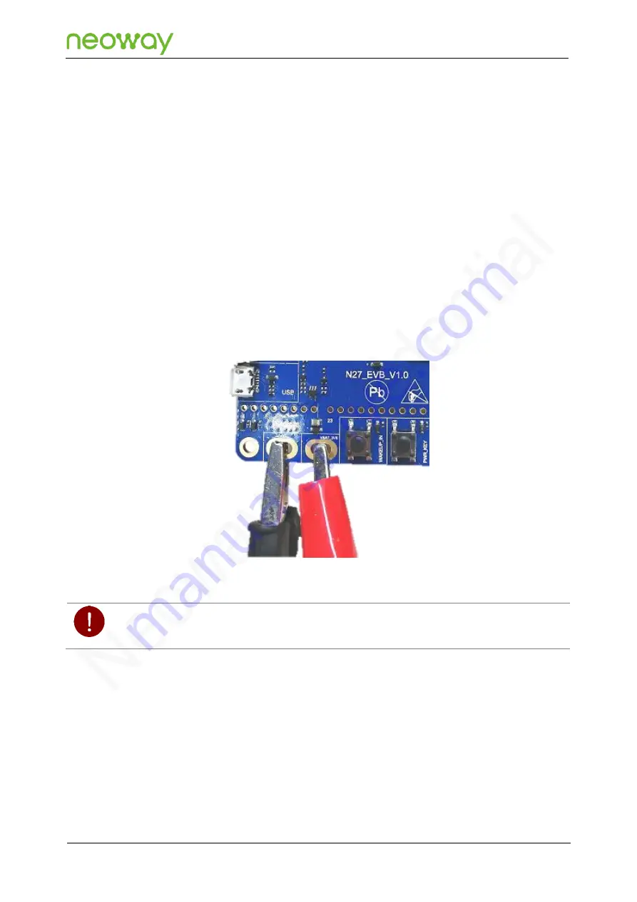
The N27 EVB provides solder pads for external power cables, as shown in Figure 3-2. The input voltage 
ranges from 3.1V to 4.3V and a 3.6V regulated power source is recommended.   

Figure 3-1 

Power pads 


The power source supplies voltage to the module directly in this manner. Do NOT connect the pads reversely or 
use a power source exceeding the requirements. Otherwise, the module will be burned and cannot be repaired

.


3.2 

Communication Connection 

3.2.1 

M5X0-PWR Board 

M5X0-PWR board is developed on PL2303 chipset by Neoway and used to convert USB to UART. You 
can also choose another USB-to-UART cable/board based on FT2232, CP210X, and other chipsets.   

Summary of Contents for N27 EVB

Page 1: ...EVK User Guide Issue 1 0 Date 2020 01 14...

Page 2: ...S INSTRUCTIONS FOR CUSTOMERS TO DESIGN THEIR APPLICATIONS PLEASE FOLLOW THE RULES AND PARAMETERS IN THIS GUIDE TO DESIGN AND COMMISSION NEOWAY WILL NOT TAKE ANY RESPONSIBILITY OF BODILY HURT OR ASSET...

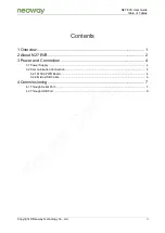
Page 3: ...Technology Co Ltd ii Contents 1 Overview 1 2 About N27 EVB 2 3 Power and Connection 4 3 1 Power Supply 4 3 2 Communication Connection 4 3 2 1 M5X0 PWR Board 4 3 2 2 Micro USB Cable 6 4 Commissioning...

Page 4: ...neers and test engineers Change History Issue Date Change Changed By 1 0 2019 12 Initial draft Cenny Xiao Conventions Symbol Indication This warning symbol means danger You are in a situation that cou...

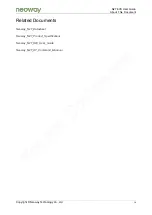
Page 5: ...7 EVK User Guide About This Document Copyright Neoway Technology Co Ltd iv Related Documents Neoway_N27_Datasheet Neoway_N27_Product_Specifications Neoway_N27_HW_User_Guide Neoway_N27_AT_Command_Mannu...

Page 6: ...erface two UART interfaces one USB interface one SIM card interface two antenna interfaces and one PWRKEY button You can connect it to a power supply and a computer through the USB cable or serial to...

Page 7: ...User Guide Chapter 2 About N27 EVB Copyright Neoway Technology Co Ltd 2 2 About N27 EVB This chapter describes the hardware layout of the N27 EVB Figure 2 1 Top view of N27 EVB Figure 2 2 1 9 7 4 3 5...

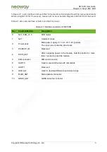
Page 8: ...terfaces and button of N27 EVB No Interface Button Description 0 N27_EVB_V1 0 EVB model 1 N27 Cellular module 2 Power pads Main power supply 3 1V to 4 3V 3 6V typically The input current shall be 2A a...

Page 9: ...2 The input voltage ranges from 3 1V to 4 3V and a 3 6V regulated power source is recommended Figure 3 1 Power pads The power source supplies voltage to the module directly in this manner Do NOT conn...

Page 10: ...e end and should be inserted into the plug of the EVB at the other end Among the 4 pin cables Green Module TXD output CMOS level Yellow Module RXD input maximum 3 3 V CMOS level Black Ground Red VBAT...

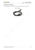
Page 11: ...User Guide Chapter 3 Power and Connection Copyright Neoway Technology Co Ltd 6 3 2 2 Micro USB Cable A micro USB cable is used to connect N27 to a computer for USB or serial communication Figure 3 2 U...

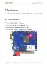
Page 12: ...bes how to connect the module and how to implement commissioning through either port 4 1 Through Serial Port Step 1 Connect the EVB board and start it 1 Use an external power source to supply power 2...

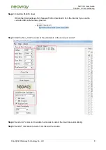
Page 13: ...r package from Neoway FAE or download it from the Internet if you use the serial to USB cable Neoway provided Step 3 Start the Neo_ComTool and set the parameters of the serial port and AT Step 4 Send...

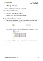
Page 14: ...3 Insert a SIM card and install an antenna onto the EVB board 4 Hold the PWRKEY_N button for 1 seconds and the module starts up Step 2 Install the N27 USB drivers on your computer 1 If your computer...

Page 15: ...Technology Co Ltd 10 5 In the page of Browse for driver software on your computer click Browse and choose the driver software path For a computer running a 32 bit OS select neoway_2019xxxx 32bit For...

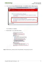
Page 16: ...echnology Co Ltd 11 6 If the computer displays Windows Security click Install this driver software anyway The installation is completed 7 Repeat steps 1 to 4 to install other drivers Step 3 Start the...

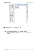
Page 17: ...nable the module to detect the baud rate automatically Step 5 Send AT commands to test or commission the module You can also upgrade the firmware of the module and capture logs through the USB port Th...

Reviews: