


N58 Hardware User Guide
Chapter 5 Application Interfaces
Copyright © Neoway Technology Co., Ltd. All rights reserved.
42
and DP signals in differential mode, and control
impedance of 90 Ω.
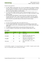
USB_ID
43
DI
USB ID pin
Leave this pin floating if it is not used.
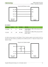
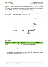
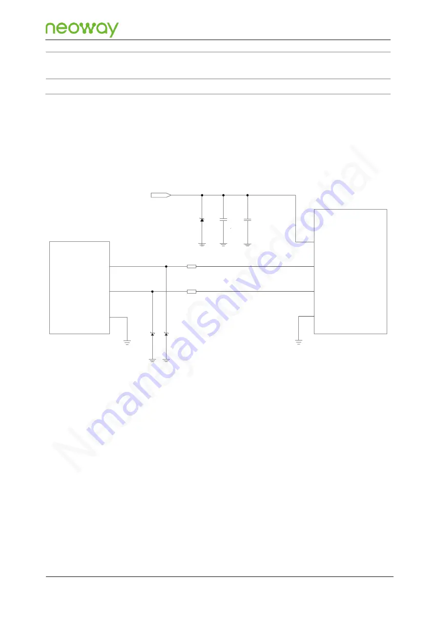
N58 can implement program download, data communications, and debugging by using the USB
interface. The module USB supports only the slave mode, and users can choose to use it according to
their needs. Figure 5-18 shows the reference design of the USB connection circuit.
Figure 5-18 Reference design of the USB connection circuit
R1
GND
USB_DM
USB_VBUS
N58 Module
USB Host
VCC ( 4. 5 V- 5. 2 V)
D 2
D 3
GND
C 2
C 1
D 1
USB_DP
R2
USB_DM
USB_DP
Schematic design guidelines:
Connect C1 (1 μF) and C2 (33 pF) filter capacitors in parallel to the USB_VBUS pin. An ESD
component must be added for the power cable.
The junction capacitance of the ESD components (D2 and D3) on USB_DP and USB_DM
cables must be less than 0.5 pF.
Connecting a resistor less than 10 Ω in series to each of the USB_DP and USB_DM cables can
effectively improve the ESD performance of the USB.
PCB design guidelines:
Place the filter capacitor on USB_VBUS as close to the module pins as possible, and place the
ESD component as close to the USB connector as possible.
Place the ESD components on USB_DP and USB_DM as close to the USB connector as
possible.


