N723-EA Hardware User Guide
Chapter 5 Application Interfaces
Copyright © Neoway Technology Co., Ltd. All rights reserved.
46
⚫
In applications with complex electromagnetic environments that have high requirements for ESD
protection, it is recommended to add ESD protection diodes (junction capacitance ≤ 7 pF) on
each signal cable.
⚫
Connect a 20 Ω resistor respectively to USIM_DATA, USIM_RST, USIM_CLK, and USIM_DET
(close to the card connector) in series to enhance the ESD performance.
⚫
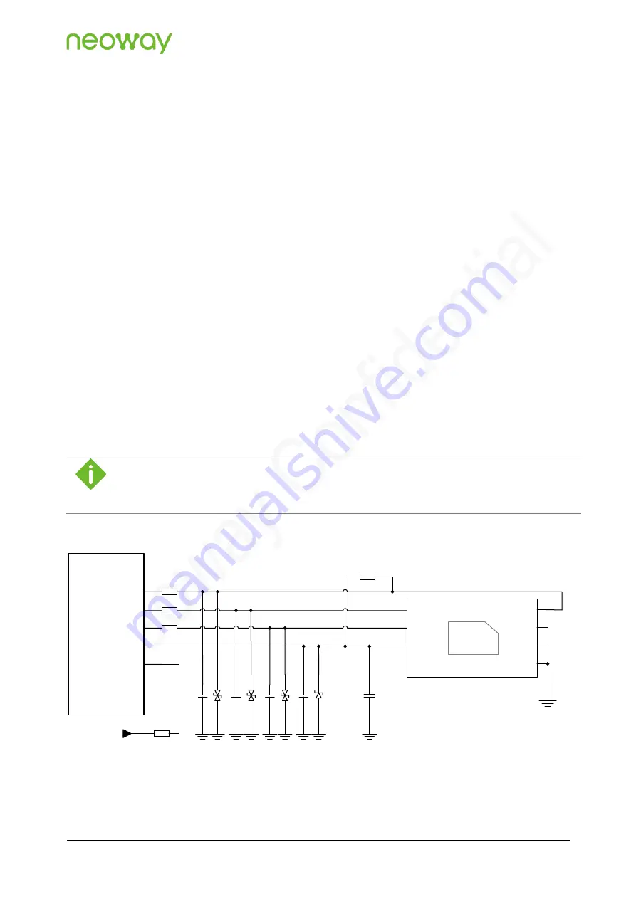
C1 - C5 are designed to place the high-frequency filter capacitors. The recommended
capacitance value is less than or equal to 10 pF. No capacitors are placed on them by default in
design. Please adjust it according to the actual debugging results.
⚫
Connect a 20 Ω resistor respectively to USIM_DATA, USIM_RST, USIM_CLK, and USIM_DET
(close to the module) in series to enhance the ESD performance.
⚫
The DET pin status of the SIM card connector in Figure 5-23 is: when the SIM card is inserted,
DET is connected to GND, and when the SIM card is pulled out, DET and GND are
disconnected.
N723-EA supports USIM card detection. USIM_DET is a 1.8 V interrupt pin. The USIM detection circuit
works by checking the levels across the USIM_DET pin before and after a USIM card is inserted. The
reference design circuit assumes that the SIM-DET is unconnected before the USIM card is inserted,
and the SIM-DET pin is grounded after the USIM card is inserted. At this time, the low level indicates
that the USIM card is detected, and the high level indicates that the USIM card is not detected. If the
insertion detection function is not required, refer to Figure 5-24.
The SIM card hot-swap function needs to be supported by the corresponding firmware version, and different the
card connector types have different configurations in firmware. If you require the SIM card hot-swap function, it is
recommended to confirm the current configuration of the module firmware with Neoway FAEs.
Figure 5-24
Reference design of the USIM card (without hot-swap) interface
N723-EA
Module
USIM_DATA
USIM_CLK
USIM_RESET
USIM_VCC
USIM_DET
20
Ω
R1
20
Ω
R2
20
Ω
R3
CLK
RST
VCC
DATA
VPP
GND
GND
DNI-47k
Ω
R4
VDD_1P8
4.7k
Ω
R5
1
μF
C5
D4
C4
D3
C3
D2
C2
D1
C1


