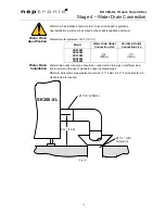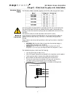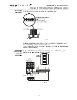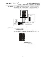
SK300-XL Steam Humidifier
27
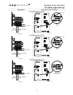
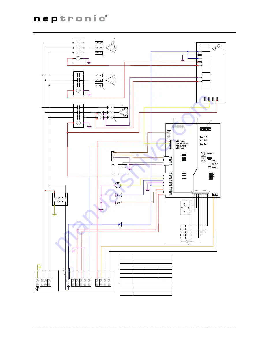
Wiring diagram
Heating
element
P
C
B9
7
081
9
REV. C
Display terminal
Flat cable to display PCB
AUTO
OFF
DRAIN
FILL
DRAIN
STEAM
CHECK
POWER ON
High temp limit switch
(Klixon)
Drain pump
Fill valve #1
Level
sensor
Level
sensor PCB
L1
L3
4
3
2
1
F
6
Terminal connection
SSR
Heating element
4-20 mA
2-10 Vdc
0-10 Vdc
No 3
-
4-20 mA
common
common
No 4
+
4-20 mA
2-10 Vdc
0-10 Vdc
No 6
RH%
Re
d
Re
d
Green
Blac
k
Blac
k
Blac
k
Green
Grey
Red
Ma
ri
n
e
Black
Black
Black
Black
Red
Red
Blue
Blue
Yellow
Red
Purple
Black
White
Orange
Red
Marine
Yellow
Brown
Red
Purple
Purple
Ma
ri
n
e
Re
d
Ma
ri
n
e
Control Signal
Whi
te
Blac
k
Or
an
g
e
Purple
Purple
Purple
Bl
ue
Black
Black
Contactor stage 1
Rocker switch
Modulating PCB
To high limit switch and differential
pressure switch
No 1 & 2
No F
24 Vac Input for modulating control(s)
Fuse
Control Panel
LED
Red
Purple
Purple
Re
d
7
8
9
Wh
it
e
Blac
k
Oran
g
e
No 7
Alarm Normally close
No 8
Alarm Normally open
No 9
Alarm common
Wh
it
e
L2
Transformer
24 Vac
TOP PCB
MODULATING
CONTROL
INPUT
HUMIDITY
INPUT
4-20mA
0-10V
2-10V
4-20mA
2-10V
0-10V
Black
Black
Black
Black
Purple
Black
Black
Red
Fill valve #2
Brown
X-
1
0
0
INP
U
T
COM
A
C
IN
A16
A17
A19
A18
GN
D
24
VAC
COM
Relay
Q1
NW
H
E
C0
02SK
Q2
-S
S
R
+
SSR
Black
Purple
Black
Black
Contactor stage 3
Contactor stage 2
Red
Red
Black
Black
Black
Yellow
Marine
Marine
Purple
Red
Red
Red
Red
Purple
Heating
element
7
8
9
4
5
6
3
1
2
Fuses
Fuses
Fuses

