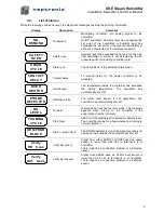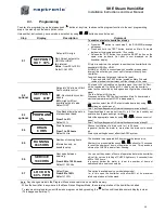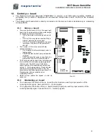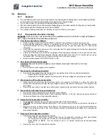
SKE Steam Humidifier
Installation Instructions and User Manual
23
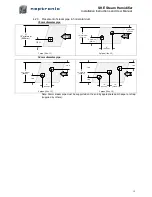
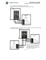
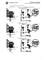
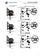
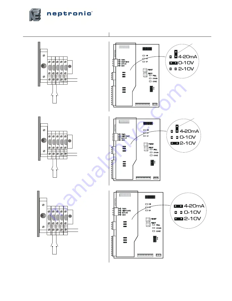
8.2.4. Control Signals
Terminal Block
Modulating Printed Circuit Board
Control signal 0-10 Vdc
(Illus. 43)
(Illus. 46)
Control signal 2-10 Vdc
(Illus. 44)
(Illus. 47)
Control signal 4-20 mA
(Illus. 45)
(Illus. 48)
1
8
7
5
4
3
2
F
6
9
0-10 Vcc
+
-
Pressure Differential
Switch
High limit
Humidistat
5 Vdc
P
C
B
9
7
0
8
1
9
R
E
V
. C
Jumper on
0-10V
Extra jumper
TOP PCB
MODULATING
CONTROL
INPUT
HUMIDITY
INPUT
4-20mA
0-10V
2-10V
4-20mA
0-10V
2-10V
1
8
7
5
4
3
2
F
6
9
2-10 Vcc
+
-
Pressure Differential
Switch
High limit
Humidistat
5 Vdc
P
C
B
9
7
0
8
1
9
R
E
V
. C
Jumper on
2-10V
Extra jumper
TOP PCB
MODULATING
CONTROL
INPUT
HUMIDITY
INPUT
4-20mA
0-10V
2-10V
4-20mA
0-10V
2-10V
1
8
7
5
4
3
2
F
6
9
4-20 mA
+
-
Pressure Differential
Switch
High limit
Humidistat
5 Vdc
Jumpers on
4-20mA & 2-10V
P
C
B
9
7
0
8
1
9
R
E
V
. C
TOP PCB
MODULATING
CONTROL
INPUT
HUMIDITY
INPUT
4-20mA
0-10V
2-10V
4-20mA
0-10V
2-10V

