SKE Steam Humidifier
Installation Instructions and User Manual
29
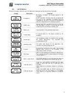
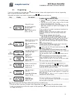
10. Control p.c. board
The Printed circuit board designated ''PCB970819" is common to all SKE series humidifier, ON/OFF or
modulating, this pc board is equipped with an advanced microprocessor which controls all the humidifier
functions.
The Printed circuit board which is directly connected onto the main pc board is installed only on modulating
model (suffix M).
10.1.
Main p.c. board
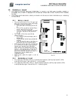
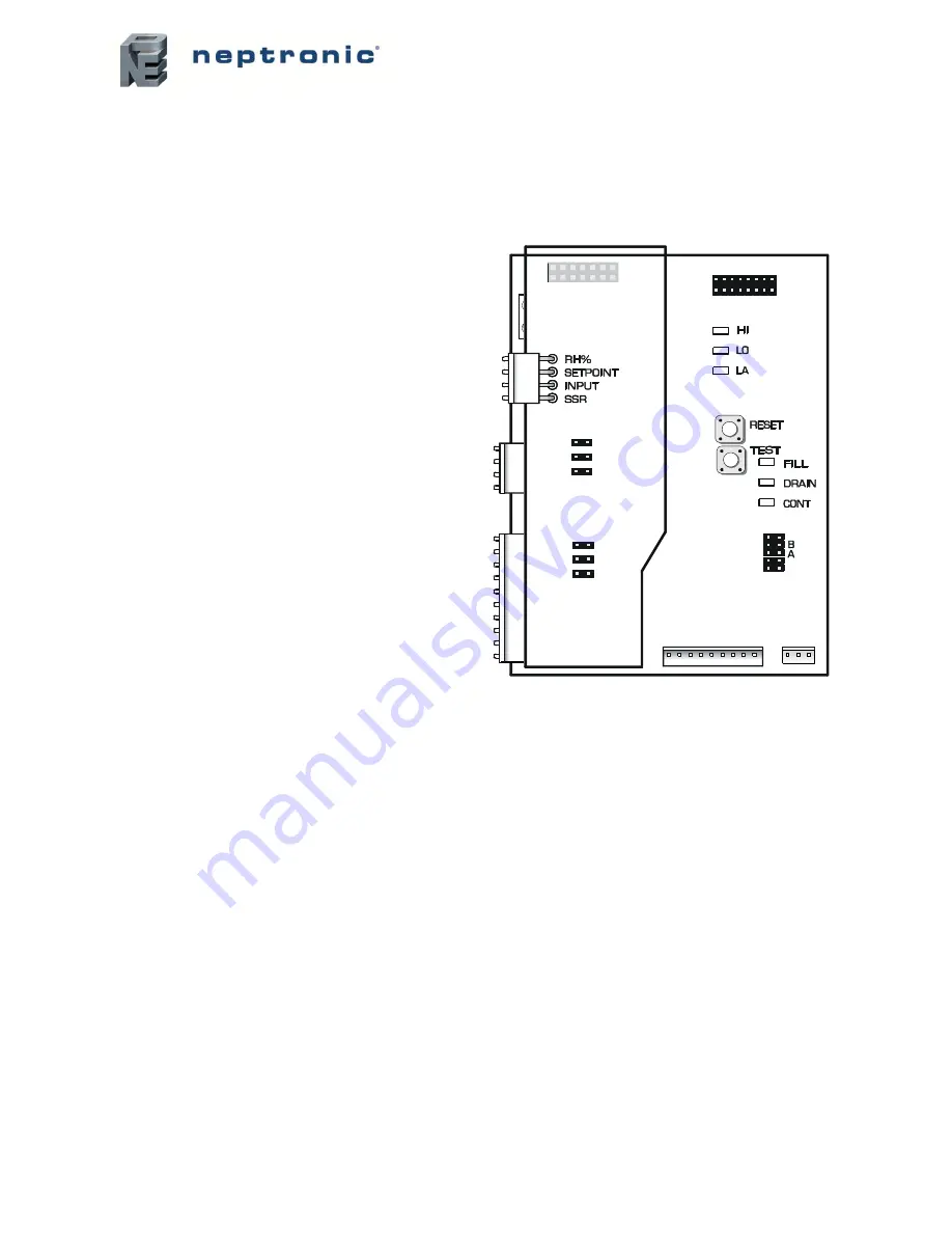
There are 3 water level L.E.D.’s in the upper right
hand side. They indicate the relative water height
as sensed by the water level sensor.
o
If HI is illuminated: water supply valve shuts
off,
o
If LO is off: An evaporation chamber filling is
ordered, water supply valve opens
o
If LA is off: No water is detected by the water
level sensor, the power to the elements is
shut off.
The 3 status L.E.D.’s at the center left side
operate as follows:
o
FILL indicates that the water supply valve is
feeding water.
o
DRAIN indicates the drain pump empties the
container.
o
CONT indicates that power is supplied to the
elements and the unit is producing steam.
TEST button should be used when commissioning
the humidifier; this will initiate a preprogrammed
start-up cycle. The start up cycle cleans the
supply water and the evaporation chamber (see
section 11 - Start-up procedure). This button also
enables to display the RH% measured by the
humidistat on humidifier display (see section 9.3 -
Programming) (this is available only on
modulating models).
RESET button enable the bypass of start up
sequence.
(Illus. 53)
10.2.
Modulating p.c. board
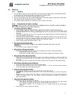
The 3 jumpers at the center of the p.c. board (Control Input) are used for proper selection of the
incoming control signal. See section 8.2.4 - Control signals.
The 3 jumpers at the bottom of the p.c. board (Humidity Input) are used for proper selection of the
incoming humidity signal. See section 8.2.3
– Humidity signals.
P
C
B
9
7
0
8
1
9
R
E
V
. C
TOP PCB
MODULATING
CONTROL
INPUT
HUMIDITY
INPUT
4-20mA
0-10V
2-10V
4-20mA
0-10V
2-10V

