background image


SKE Steam Humidifier 

Installation Instructions and User Manual 


3. 

Mechanical installation 

3.1. 

General recommendations 


CAUTION

:  RISK  OF  ELECTRIC  SHOCK.  DISCONNECT  THE  APPLIANCE  FROM  THE  ELECTRIC 

SUPPLY BEFORE TO PROCEED TO INSTALLATION. 


IMPORTANT

:  Mechanical installation should conform to local codes and regulations. 


Location: Plan a location easy to access in order to permit an easy inspection and servicing of the humidifier. 
Do  not  install  humidifier  where  failure  of  the  appliance  could  cause  damage  to  the  building  structure  or  to 
costly equipment. 
This location should be well ventilated; the ambient temperature should not exceed 30

C. 


Typically, the total steam line length between the humidifier and the steam distributor depends on the steam 

line material type: 


For  flexible  steam  hose:  the  total  steam  line  length  should  not  exceed  5  meters.  For  longer  distances 
use insulated hard piping. 


For  insulated  hard  piping:  the  total  steam  line  length  should  be  determined  by  the  humidifier  capacity: 
0,67m  for  each  kg/h  capacity  of  the  humidifier,  with  a  maximum  of  15  m.  For  longer  steam  line  runs, 
consult factory. 


3.2. 

Positioning 


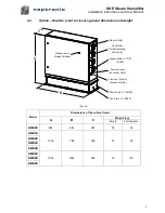
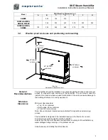
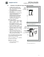
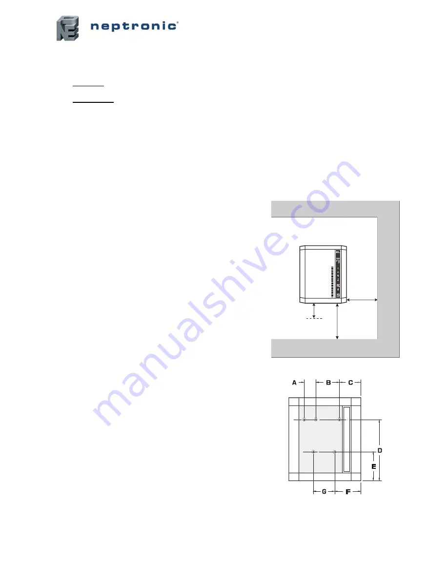
The  front  panel  and  the  right  side  (electrical  compartment) 
should be accessible in order to permit the servicing. 
Leave  a  clearance  of  at  least  1,25m  to  the  front  panel  and 
0,6m to the right side. 


The  humidifier  should  be  mounted  at  a  minimum  of  1m  to 
1,2m above floor level. 
Leave  a  clearance  of  at  least  0,25m  under  the  humidifier  for 
installation  of  water  supply,  drain  piping  and  electrical 
connections. 
 

3.3. 

Wall mounting 


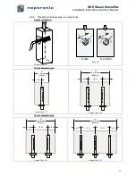
Use the keyholes located on the back panel of the humidifier. 


Before  to  proceed  to  the  wall  mounting,  take  off  the 
Evaporation  chamber  sub  assembly  (see  section  12, 
Servicing).  


Check  the  solidity  of  the  chosen  support  or  wall  (bricks, 
concrete,  stud  partition  wall,  etc)  on  which  the  humidifier  will 
be mounted. 


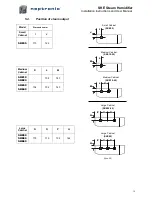
Drill  holes  for  the  upper  anchors  (holes  with  eyelet)  into  the 
support  or  wall  as  per  dimensions  specified  in  the  table 
(illus.4). 
The  holes  dimensions  (diameter  and  depth)  should  by  in 
accordance with the recommendations of the chosen anchors. 


Install then bolt anchors, if required. 


Screw-on the 2 or 3 upper screws (holes with eyelet) of a 
minimum diameter of #10 (6mm) (screws are not supplied). 
Leave a clearance between head screws and wall in order to 
permit the mounting of the humidifier. 


Use the keyholes located on the back panel of the humidifier. 


Hang on the humidifier to the 2 or 3 screws; it is preferable let 
the front door open during this operation. 
According to the size and weight of the humidifier, you may 
need the help of a second person to assist you.  


When the humidifier is positioned on the upper screws, tighten 
the screws to secure the humidifier. 


If applicable, install and secure lower screws. 


Positioning

 (Illus. 3) 


Front view 

(Illus. 4)


(0,60 m)

(0,25 m)

(1 to 1,2 m)

10'’

24'’

39 to 48'’

E

n e p t r o n ic

Summary of Contents for SKE SERIES

Page 1: ...SKE ENG 170816 Steam Humidifier SKE series Installation instruction user manual READ AND SAVE THESE INSTRUCTIONS HUMIDITY 45 RH...

Page 2: ...r installation and operation as per the manufacturer s recommendations The application of these instructions is one of the conditions for the application of the warranty The application of these instr...

Page 3: ...aps on the steam line 14 5 4 Position of steam output 15 5 5 Installation of humidifier with Space Distribution Unit SDU 16 6 Plumbing connection 17 6 1 Water supply 17 6 2 Drain connection 18 6 3 Wea...

Page 4: ...emale compression fitting DN20 hydraulic for the drain output of the evaporation chamber 1 female compression fitting DN15 hydraulic for the drain output of the drip pan 1 flexible hose for the water...

Page 5: ...r and a cover equipped with one or several heater elements It is the heart of the humidifier which produce steam 1 2 2 SDU Space Distribution Unit Integrated steam distribution unit optional on certai...

Page 6: ...E30 Medium 724 533 318 324 1048 SDU 3 SKE40 Medium 724 533 318 324 1048 SDU 3 SKE50 Large 794 813 318 110 50 205 93 SKE60 Large 794 813 318 SKE80 Large 794 813 318 Options On modulating humidifier the...

Page 7: ...PT DN15 Pan Drain DN20 Main Drain DN20 Electrical Control Knockout Hole Power Supply Knockout Hole Heat Sinks for Modulating Units only B A C Alphanumeric Display Window Illus 2a Model Dimensions of t...

Page 8: ...humidifier should be mounted at a minimum of 1m to 1 2m above floor level Leave a clearance of at least 0 25m under the humidifier for installation of water supply drain piping and electrical connect...

Page 9: ...for inspection and servicing of the humidifier The unit should never be installed in a location where unusual malfunction of the unit can cause damage to the building structure or to costly equipment...

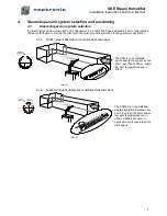
Page 10: ...he most economical solution for any particular application 4 1 1 S A M steam absorption manifold Horizontal duct Illus 5 The SAM is to be installed where absorption distances are short less than 1500m...

Page 11: ...olution 4 1 4 Multi Steam system Illus 8 The Multi Steam system is to be installed in critical locations in air handling systems particularly where absorption distances are very short less than 900mm...

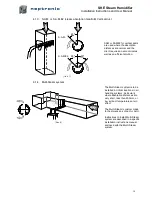
Page 12: ...hole size in the duct must be as per table below Steam manifold Hole size A 35mm 51mm 54mm 78mm Illus 9 WARNING Risk of condensing Ensure that the minimum distance of the end of the manifold is at le...

Page 13: ...llus 12 54mm diameter pipe 2 pipes Illus 13 3 pipes Illus 14 Note 54mm steam pipe must be supported on the end by appropriate duct hanger or strap supplied by others H 10 minimum 250mm 1 3 H air air H...

Page 14: ...orientation 3D view Illus 15 Illus 16 35mm diameter pipe 1 pipe Illus 17 2 pipes Illus 18 54mm diameter pipe 2 pipes Illus 19 3 pipes Illus 20 air air 45 air 45 S A M S A M E2 W 10 minimum 250mm 1 2...

Page 15: ...henever possible use insulated copper piping Flexible steam hose should be used for short runs up to 5m or for interconnecting between the rigid pipes c Whenever using rigid copper these ones should b...

Page 16: ...ns mm Small Cabinet I J SKE05 110 122 Medium Cabinet K L M SKE10 SKE20 102 143 SKE30 SKE40 134 102 143 Large Cabinet N O P Q SKE50 SKE60 SKE80 179 179 132 144 Illus 25 I J L M Small Cabinet SKE05 Medi...

Page 17: ...e SDU to the wall on brackets not supplied do not drill mounting holes thru the cabinet of the SDU Connect the steam hose s to the bottom inlet s of the SDU to the top of the steam outlet s of the hum...

Page 18: ...30 C maximum 3 8 DN10 standard copper water line connection A shut off valve not supplied should be installed in the water supply line to the unit close to the humidifier to facilitate servicing It i...

Page 19: ...evacuating into the same drain line 6 3 Weather proof enclosure plumbing connection Pan Drain DN20 Main Drain DN20 Copper pipe by others field installed for connection to side outlets Supply Water NPT...

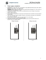
Page 20: ...oppers conductors An external over current protection and disconnect circuit breaker should be installed on the supply adjacent to the humidifier A knock out not supply should be installed at the bott...

Page 21: ...80 Illus 34 5 Vdc Low voltage control terminal block High voltage power terminal block Humidistat High limit Pressure Differential switch 5 Vdc 1 2 2 1 7 8 9 humidistat 24 VAC Pressure Differential sw...

Page 22: ...HC80 as space sensor Illus 36 1 8 7 5 4 3 2 F 6 9 1 3 2 COMMON 0 10 VDC OUTPUT 24 VAC OR VDC SHR10 or SHC80 SKE To Term 3 To Term F To Term 6 1 8 7 5 4 3 2 F 6 9 SKE To Term 3 To Term F To Term 4 1 3...

Page 23: ...dc PCB970819 REV C Jumper on 0 10V Extra jumper TOP PCB MODULATING CONTROL INPUT HUMIDITY INPUT 4 20mA 0 10V 2 10V 4 20mA 2 10V 0 10V 1 8 7 5 4 3 2 F 6 9 2 10 Vcc Pressure Differential Switch High lim...

Page 24: ...819 REV C Jumper on 0 10V Extra jumper TOP PCB MODULATING CONTROL INPUT HUMIDITY INPUT 4 20mA 0 10V 2 10V 4 20mA 0 10V 2 10V 1 8 7 5 4 3 2 F 6 9 2 10 Vcc Pressure Differential Switch High limit Humidi...

Page 25: ...uct humidistat must always be located before any outside air intake in order to ensure accurate sensing of the air from the humidified space Alternatively a room humidistat can be used The room humidi...

Page 26: ...tions of operation 5 FILL indicator O Indication that the water supply fill valve is open O Indication that the water supply fill valve is closed 6 STEAM indicator O For ON OFF models the STEAM indica...

Page 27: ...Duct Relative Humidity readings Only on modulating humidifiers suffix M If no High limit Duct sensor is installed second line is left blank kg hr 8 Quantity of steam produced by the humidifier I e The...

Page 28: ...e inside the container has exceeded the boiling temperature The humidifier has automatically shut off PROBE DEFECTED Defective probe The water level sensor is not operational The humidifier has automa...

Page 29: ...ct the VAV Set point value desired by using buttons on control panel Note This Step will appear only if Internal has been selected at step 01 03 optional Prop Band allows the set up of proportional ba...

Page 30: ...L indicates that the water supply valve is feeding water o DRAIN indicates the drain pump empties the container o CONT indicates that power is supplied to the elements and the unit is producing steam...

Page 31: ...5 Push the TEST button located on the main pc Board This pc Board is located in the electrical compartment 6 This will start up a pre programmed start up cycle This start up cycle will test functions...

Page 32: ...FIER Turn off the main power supply to the humidifier 3 Disconnection of heating element s Remove the high voltage connector located at the top right hand side of the mechanical compartment o Model SK...

Page 33: ...over itself should be cleaned as necessary only if some scale has been accumulated on them Proceed as per the cleaning of the container step 8 Removing and cleaning of the water level sensor A chamber...

Page 34: ...rature switch klixon and the high voltage connector of the heating element CAUTION RISK OF FIRE MAKE SURE THE HIGH VOLTAGE CONNECTOR IS PROPERLY LOCKED AN UNPROPER CONNECTION MAY PROVOKE ELECTRIC ARCS...

Page 35: ...al 34 13 Exploded view Bill of Material 13 1 Exploded view Illus 55 A B A B C C D D E E F F G G H I I J J N O P Q R T U V W X Y Steam Trap Assem bly Plastic gril SDU Cabinet Evaporation cham ber base...

Page 36: ...D ASSY SKE50 to SKE80 SW FOAMLG ASSY J Water level sensor SKE05 SW PROBSM ASSY SKE10 20 SW PROBMD ASSY SKE30 40 50 60 80 SW PROBLAR ASSY K Water supply valve SKE05 to SKE80 SP 6007 L Fill and drain tr...

Page 37: ...0V 3 400V 3 400V 3 400V 3 400V 3 400V 3 D Heater element SW 5937 SW 5980 SW 5983 SW 5981 SW 5982 SW 5983 SW 5955 SW 5984 SW 5983 SW 5955 R Transformer SP 3365 SP 3374 SP 3365 SP 3374 SP 3374 SP 3374 S...

Page 38: ...on Check the operation of the high limit humidistat Verify the connections of the wires to the control terminal blocks Check Off Fill Off Steam Off Drain Off Humidifier does not produce steam Safety O...

Page 39: ...Check On Fill Off Steam Off Drain Off Humidifier is not operating and the CHECK light is ON Power On The water level sensor is damaged Replace the water level sensor item J Check On Fill Off Steam Of...

Page 40: ...u blvd Montreal Qc H4N 1R6 Canada www neptronic com Toll free in North America 1 800 361 2308 Tel 514 333 1433 Fax 514 333 3163 Customer service fax 514 333 1091 Monday to Friday 8 00am to 5 00pm East...

Reviews: