background image


SKE-XL Steam Humidifier 

Installation Instructions and User Manual


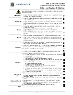
Handling & Unpacking 


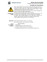
Lifting or handling MUST only be carried out by trained and qualified personnel. Ensure 
that  the  lifting  operation  has  been  properly  planned,  risk  assessed  and  that  all 
equipment  has  been  checked  by  a  skilled  and  competent  Health  &  Safety 
representative and effective control measures put in place. 
It is the customer’s responsibility to ensure that operators are trained in handling heavy 
goods and to enforce the relevant lifting regulations. 

Refer to Dimensions & Weight section for system dry weights. 

Handling and 

Lifting  

The  SKE-XL  Steam  Humidifier  MUST  always  be  handled  and  lifted  with  care  and 
should remain in its original packaging for as long as possible prior to installation 

The  SKE-XL  Steam  Humidifier  package  may  be  carried  using  a  forklift  from  the 
underside. Caution should be exercised to ensure balanced load before lifting. 

Lifting sling angle should be greater than 30

˚ to the horizontal. 


Unpacking 

SKE-XL Steam Humidifier is shipped on a wooden crate. 

Remove packing wooden crate and skids prior to installation. 


List of 

accessories 

supplied 

Standard enclosure 


  2 sets of keys.


  2 adjustable steam hose collars per steam outlet.


  The present 

Installation Instructions and User Manual

.


Wiring diagram

 affixed onto the interior of the electrical compartment door.


!

Summary of Contents for SKE-XL

Page 1: ...Electric Steam Humidifier SKE90 100 110 120 Series SKE XL INSTALLATION INSTRUCTIONS Read and save these instructions SKE XL IOM Rev 170322...

Page 2: ...lean and disinfect the humidification system Have a competent person carry out a risk assessment of the water system supplying the humidifier to ensure the water supply is of an acceptable quality COR...

Page 3: ...f your installation and operation as per the manufacturer s recommendations The application of these instructions is one of the conditions for the application of the warranty The application of these...

Page 4: ...d Mounting 9 Stage 2 Steam Distribution Installation 10 Stage 3 Water Supply Installation 13 Stage 4 Water Drain Connection 14 Stage 5 Electrical Supply and Installation 15 Stage 6 Electrical Control...

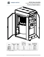
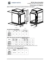
Page 5: ...Steam cap kg h Power kW Current A Nb of outlets Multi Steam header diam mm 400V 3ph SKE90 90 66 96 1 76 mm SKE100 100 74 107 1 76 mm SKE110 110 82 119 2 76 mm SKE120 120 90 130 2 76 mm Notes Maximum...

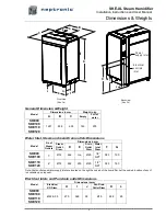
Page 6: ...m Steam Outlet Diam D E Drain Outlet Diam Water Inlet Diam F G SKE90 SKE100 1 76 462 n a 20 1 2 NPT 383 190 SKE110 SKE120 2 76 462 230 20 1 2 NPT 383 190 Note Drain outlet and water supply inlet are l...

Page 7: ...Model No of Steam Outlets Dimensions in mm Steam Outlet Diam D E Drain Outlet Diam Water Inlet Diam F G SKE90 SKE100 1 76 109 1291 20 NPT 383 190 SKE110 SKE120 1 100 109 1291 20 NPT 383 190 Note Steam...

Page 8: ...weights Handling and Lifting The SKE XL Steam Humidifier MUST always be handled and lifted with care and should remain in its original packaging for as long as possible prior to installation The SKE...

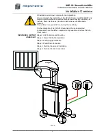
Page 9: ...opriate training The customer is responsible for ensuring their suitability For the installation of the SKE XL Steam Humidifier and associated components there should be no special tooling requirement...

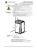
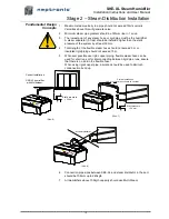
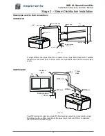
Page 10: ...sure the steam hose length is kept to the shortest possible length For flexible steam hose the total steam line length should not exceed 5 meters For longer distances use insulated hard piping For ins...

Page 11: ...ould not exceed 5 m or insulated rigid piping should not exceed 15 m 5 Whenever possible use rigid copper piping flexible steam hose can be used for short runs or for interconnecting between rigid pip...

Page 12: ...ze Multi Steam units so that they can be placed side by side 3 For installation of Multi Steam units please refer to Neptronic Multi Steam Installation Instructions Horizontal duct Illus 9 Vertical du...

Page 13: ...allow a 15mm condensate drain from the main steam supply SKE110 120 Illus 12 Two 76mm steam outlets to a single 130mm feed pipe should be connected to a single Multi Steam with a suitable reduction a...

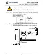
Page 14: ...ater Maximum water supply pressure 70 to 480kPa Minimum water temperature 4 C Maximum water temperature 40 C Model Water inlet Connection size SKE90 SKE100 SKE110 SKE120 15 mm Water supply line Instal...

Page 15: ...ected to drain pipe of sufficient size We recommend the use of 20mm minimum standard copper hydraulic pipes Minimum water drain pipe gradient should be 1 5mm in 1m horizontal run No drain trap is requ...

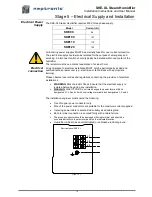
Page 16: ...nicians with appropriate training Please observe local codes and regulations concerning the provision of electrical installations WARNING Risk of electric Shock Ensure that the electrical supply is is...

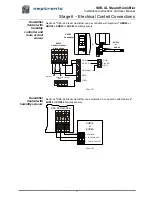
Page 17: ...pening of any on this contact Operation of humidifier will stop and Alarm message will be displayed Humidifier Control with humidity controller Neptronic SKE XL modulating Steam Humidifier can be inst...

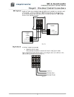
Page 18: ...ors Illus 18 Humidifier Control with humidity sensors Neptronic SKE XL Steam Humidifier can be installed in conjunction with Neptronic SHR10 or SHC80 humidity sensors Illus 19 humidistat High limit 1...

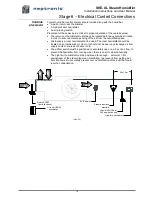
Page 19: ...Duct humidity controller Illus 20 Dry Contacts 2 volt free contacts are provided Operation fan contacts One normally connected to common and one normally open contact These contacts should be used to...

Page 20: ...sed The room humidistat should be located on an inside wall or column It should not be near any discharge air from supply ducts or sources of heat or cold The airflow switch must be positioned to accu...

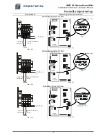
Page 21: ...B970819 REV C Jumper on 0 10V Extra jumper TOP PCB MODULATING CONTROL INPUT HUMIDITY INPUT 4 20mA 0 10V 2 10V 4 20mA 2 10V 0 10V 1 8 7 5 4 3 2 F 6 9 2 10 Vcc Pressure Differential Switch High limit Hu...

Page 22: ...70819 REV C Jumper on 0 10V Extra jumper TOP PCB MODULATING CONTROL INPUT HUMIDITY INPUT 4 20mA 0 10V 2 10V 4 20mA 2 10V 0 10V 1 8 7 5 4 3 2 F 6 9 2 10 Vcc Pressure Differential Switch High limit Humi...

Page 23: ...he disconnect switch 11 Confirm the control signal is matching control signal jumper on Main PCB Start up 12 Proceed to start up the Humidifier as follows a Open the front access door of the humidifie...

Page 24: ...exceeded the Service hours see section 12 Service O No abnormal conditions of operation 5 FILL indicator O Indication that the water supply fill valve is open O Indication that the water supply fill v...

Page 25: ...lay Space and Duct Relative Humidity readings Only on modulating humidifiers suffix M If no High limit Duct sensor is installed second line is left blank Quantity of steam produced by the humidifier I...

Page 26: ...ctivated OVER HEATED Overheated The temperature inside the container has exceeded the boiling temperature The humidifier has automatically shut off PROBE DEFECTED Defected probe The water level sensor...

Page 27: ...e VAV Set point value desired by using buttons on control panel Note This Step will appear only if Internal has been selected at step 01 03 optional Prop Band allows the set up of proportional band Fr...

Page 28: ...er supply valve is feeding water o DRAIN indicates the drain valve empties the container o CONT indicates that power is supplied to the elements and the humidifier is producing steam TEST button shoul...

Page 29: ...d Marine Control Signal White Black Orange Purple Purple Purple Blue Black Black Contactor stage 1 Rocker switch Modulating PCB To high limit switch and differential pressure switch No 1 2 No F 24 Vac...

Page 30: ...SKE XL Steam Humidifier Installation Instructions and User Manual 29 Notes...

Page 31: ...SKE XL Steam Humidifier Installation Instructions and User Manual 30...

Page 32: ...Neptronic Head office 400 Blvd Lebeau Montreal Qc H4N 1R6 CANADA Tel 1 514 333 1433 Fax 1 514 333 3163 www neptronic com 2017...

Reviews: