background image

SKE Humidifier 

User Manual


 34 


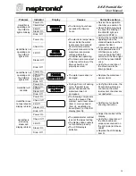
Problem


Indicator


Display


Causes


Corrective actions


Power: On 

Check: Blink 

Fill: Off 

Steam: On 

Humidfier is 

operating and 

the CHECK 

light is blinking 

Drain: Off 

SC RO LL

M O D E

 The Running hours have 

exceeded the Service 
hours. 

 Service the evaporation 

chamber, see section 14. 

 Reset the Running hours 

to cancel the blinking of 
the CHECK light, see 
section 9.2 STEP 3. 

Power: On 

Check: On 

Fill: Off 

Steam: Off 

Humidifier is not 

operating and 

the CHECK 

light is ON 

Drain: Off 

O V E R

H E A T E D

 The electronic temperature 

sensor inside the water 
level sensor had sensed 
abnormal temperature. 

 The quick connector to the 

water level sensor was 
removed while the 
humidifier was operating. 

 The brown wire connected 

to the top left corner of the 
Main pc board is not 
properly secured. 

 Verify if the humidifier was 

operating below the 
standard water level then 
replace the item J. 

 If connector was removed 

while powered was still 
ON then press on the 
main pc board the TEST 
button until the Drain light 
is ON then press RESET 
once. 

 Verify the connection of 

the brown wire to the 
Main pc board. 

Power: On 
Check: On 
Fill: Off 
Steam: Off 

Humidifier is not 

operating and 

the CHECK 

light is ON 

Drain: Off 

P RO B E

D E F E C TE D

 The water level sensor is 

damaged. 

 Replace the water level 

sensor, item J. 

Power: On 
Check: On 
Fill: Off 
Steam: Off 

Humidifier will 

not drain 

Drain: Off 

D RN /P R O B

B L O C K

 During a Drain or Foaming 

cycle, the water level 
sensor has sensed the 
water level has not 
decreased. 

 Verify the drain valve, the 

fill and drain water pipe 
connection, the water 
level sensor chamber are 
not obstructed. 

Power: On 

Check: Off 

Fill: Off 

Steam: Off 

Humidifier does 
not operate and 

display is blank 

Drain: Off 

 The following components 

can be the cause of this 
problem: water level sensor 
(item J), main pc board 
(item U), modulating pc 
board (item V) or the LCD 
display (item N). 

 Call factory for trouble 

shooting instruction. 

Power: On 

Check: Off 

Fill: Off 

Steam: On 

Humidifier is 

producing 

steam and 

display is blank 

Drain: Off 

 The potentiometer contrast 

is set at the lowest setting. 

 The display ribbon cable is 

not connected properly. 

 The LCD display is 

defective. 

 Adjust the contrast of the 

display. 

 Verify the connections of 

the ribbon cable are 
properly secured and on 
the right side (red line on 
cable). 

 Replace the LCD display, 

item N. 


Summary of Contents for SKE

Page 1: ...SKE ENG 110221 doc Steam Humidifier SKE series HUMIDITY 45 RH Installation instruction user manual READ AND SAVE THESE INSTRUCTIONS...

Page 2: ...oducts Ltd Manufacturer Presentation National Environmental Products Ltd NEP is the owner of the brand Neptronic NEP develops manufactures and services a complete line of Steam humidifiers Humidistat...

Page 3: ...n of humidifier with Space Distribution Unit SDU 13 6 Plumbing connection 14 6 1 Water supply 14 6 2 Drain connection 15 7 Power supply connections 15 8 Low voltage control connections 16 8 1 ON OFF H...

Page 4: ...male cmpression fitting hydraulic for the drain output of the evaporation chamber 1 female compression fitting hydraulic for the drain output of the drip pan 1 female fitting for the water supply conn...

Page 5: ...xternal fan relay on a call for humidity SF SK300FANRELAY 1 2 Definition 1 2 1 Evaporation chamber Assembly including the metal cylinder and a cover equipped with one or several heater elements It is...

Page 6: ...SKE20 20 15 22 1 35 Medium 724 533 318 165 890 SDU 2 SKE30 30 22 33 2 35 Medium 724 533 318 324 1048 SDU 3 SKE40 40 30 44 2 35 Medium 724 533 318 324 1048 SDU 3 SKE50 50 36 53 2 54 Large 794 813 318...

Page 7: ...se the keyholes located on the back panel of the humidifier Before to proceed to the wall mounting take off the Evaporation chamber sub assembly see section 12 Servicing Check the solidity of the chos...

Page 8: ...solution for any particular application 4 1 1 S A M steam absorption manifold Horizontal duct air Illus 5 The SAM is to be installed where absorption distances are short less than 1500mm and or low d...

Page 9: ...an efficient solution 4 1 4 Multi Steam system air Illus 8 The Multi Steam system is to be installed in critical locations in air handling systems particularly where absorption distances are very shor...

Page 10: ...duct must be as per table below Steam manifold Hole size A 35mm 51mm 51mm 78mm 5 120mm 5 120mm A Illus 9 WARNING Risk of condensing Ensure that the minimum distance of the end of the manifold is at le...

Page 11: ...1 air H 10 minimum 250mm 3 minimum 80mm 8 200mm 6 minimum 150mm 2 pipes Illus 12 51mm diameter pipe H 24 minimum 600mm 1 5 H 2 5 H 8 200mm air 2 pipes Illus 13 H 36 minimum 900mm 1 6 H 1 2 H 1 3 H 10...

Page 12: ...D view Illus 15 air 45 air 45 S A M S A M E2 Illus 16 35mm diameter pipe W 10 minimum 250mm 1 2 W 1 pipe Illus 17 W 24 minimum 600mm 1 2 W 1 4 W 1 4 W 2 pipes Illus 18 51mm diameter pipe W 24 minimum...

Page 13: ...condensation losses Whenever possible use insulated copper piping Flexible steam hose should be used for short runs up to 5m or for interconnecting between the rigid pipe runs c Whenever using rigid c...

Page 14: ...t I J SKE05 110 122 Medium Cabinet K L M SKE10 SKE20 102 143 SKE30 SKE40 134 102 143 Large Cabinet N O P Q SKE50 SKE60 SKE80 179 179 132 144 I J L M Small Cabinet SKE05 Medium Cabinet SKE10 20 Medium...

Page 15: ...from the humidifier remote SDU Please follow the piping recommendations section 5 2 Mount the SDU to the wall on brackets not supplied do not drill mounting holes thru the cabinet of the SDU Connect...

Page 16: ...sure 0 7 to 4 8 bars 10 to 70 psig Maximum temperature 30 C maximum 3 8 standard copper water line connection A shut off valve not supplied should be installed in the water supply line to the unit clo...

Page 17: ...block designated L1 L2 and L3 with Low voltage terminal block designated 1 2 and 3 The wiring to the Humidifier should be done by a qualified electrician and conforming to the procedure regulation and...

Page 18: ...ection to the Humidifier control terminal block Connection to HRO20 humidistat or HRO20 with remote humidity sensor SHR10 or SHC80 humidistat 24 VAC Pressure Differential switch High limit 1 4 3 2 F 8...

Page 19: ...stem with humidity controlled by humidifier using SHC80 as Hi limit duct sensor and SHR10 or SHC80 as space sensor 1 8 7 5 4 3 2 F 6 9 SKE To Term 3 To Term F To Term 4 1 3 2 COMMON 0 10 VDC OUTPUT 24...

Page 20: ...0V 4 20mA 0 10V 2 10V Illus 40 Humidity signal 2 10 Vdc 1 8 7 5 4 3 2 F 6 9 2 10 Vcc Pressure Differential Switch High limit Humidistat 5 Vdc Illus 38 PCB970819 REV C Jumper on 2 10V Extra jumper TOP...

Page 21: ...mA 0 10V 2 10V Illus 46 Control signal 2 10 Vdc 1 8 7 5 4 3 2 F 6 9 2 10 Vcc Pressure Differential Switch High limit Humidistat 5 Vdc Illus 44 PCB970819 REV C Jumper on 2 10V Extra jumper TOP PCB MODU...

Page 22: ...operation of the overall system The return duct humidistat must always be located before any outside air intake in order to ensure accurate sensing of the air from the humidified space Alternatively a...

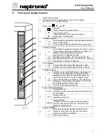
Page 23: ...FILL indicator O Indication that the water supply fill valve is open O Indication that the water supply fill valve is closed 6 STEAM indicator O ON OFF model the STEAM indicator lights when the contac...

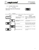
Page 24: ...t Relative Humidity readings Only on modulating humidifiers suffix M If no High limit Duct sensor is installed second line is left blank k g h r 8 Quantity of steam produced by the humidifier I e The...

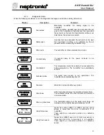
Page 25: ...R H E A T E D Overheated The temperature inside the container has exceeded the boiling temperature The humidifier has automatically shut off P R O B E D E F E C T E D Defected probe The water level s...

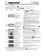
Page 26: ...he VAV Set point value desired by using buttons on control panel Note This Step will appear only if Internal has been selected at step 01 03 optional PROPBAND 3 Prop Band allows the set up of proporti...

Page 27: ...tes that the water supply valve is feeding water o DRAIN indicates the drain valve empties the container o CONT indicates that power is supplied to the elements and the unit is producing steam TEST bu...

Page 28: ...button located on the main pc Board This pc Board is located in the electrical compartment 6 This will start up a pre programmed start up cycle This start up cycle will test functions of the humidifie...

Page 29: ...main power supply to the humidifier 3 Disconnection of heating element s Remove the high voltage connector located at the top right hand side of the mechanical compartment o Model SKE05 Unscrew the co...

Page 30: ...Proceed as per the cleaning of the container step 8 Removing and cleaning of the water level sensor A chamber protects the water level sensor Cleaning of the sensor requires removing this chamber o U...

Page 31: ...on and the high voltage connector of the heating element CAUTION RISK OF FIRE MAKE SURE THE HIGH VOLTAGE CONNECTOR IS PROPERLY LOCKED AN UNPROPER CONNECTION MAY PROVOKE ELECTRIC ARCS 11 Start up of th...

Page 32: ...view Bill of Material 13 1 Exploded view A B A B C C D D E E F F G G H I I J J N O P Q R T U V W X Y Steam Trap Assem bly Plastic gril SDU Cabinet Evaporation cham ber base SKE10 to SKE80 Evaporation...

Page 33: ...FOAMLG ASSY SKE05 SW PROBSM ASSY SKE10 20 SW PROBMD ASSY J Water level sensor SKE30 40 50 60 80 SW PROBLAR ASSY SP 6003 K Water supply valve SKE05 to SKE80 SP 6007 IDC SKE05 SW TRAPSMA P SKE10 to SKE...

Page 34: ...400V 3 400V 3 400V 3 D Heater element SE 5937 SE 5980 SE 5983 SE 5981 SE 5982 SE 5983 SE 5955 SE 5984 SE 5983 SE 5955 R Transformer SP 3365 SP 3374 SP 3365 SP 3374 SP 3374 SP 3374 S Contactor SP 3080...

Page 35: ...an operation Check the operation of the high limit humidistat Verify the connections of the wires to the control terminal blocks Power On Check Off Fill Off Steam Off Humidifier does not produce steam...

Page 36: ...ction of the brown wire to the Main pc board Power On Check On Fill Off Steam Off Humidifier is not operating and the CHECK light is ON Drain Off PROBE DEFECTED The water level sensor is damaged Repla...

Page 37: ...SKE Humidifier User Manual 35 Personal notes...

Page 38: ...SKE Humidifier User Manual 36 Personal notes...

Page 39: ...losses that may arise for any reason whatsoever as a result of our failure to adhere to such promises 10 Return of good Goods received by the purchaser cannot be returned unless a completed R M A For...

Reviews: