background image


SKE4-E Steam Humidifier 

Installation Instructions and User Manual 


www.neptronic.com


Page | - 1 - 


Foreword 

Neptronic Company Overview 

F

ded   1976,  e e a 

a e c

a

  ha  de g ,  a fac

e  a d d

b e  

d c  f  

the  HVAC  industry.  Our  product  line  includes  intelligent  controllers,  electronic  actuators,  actuated 
valves, humidifiers and electric heaters.  
 
Our products are designed and manufactured by over 250 dedicated employees in our 7,500 m

2

 (80,000 

ft

2

) state-of-the-art facility located in Montreal, Canada. Using a vertical integration model, our entire 

manufacturing chain is under one roof, from software and hardware development, to SMT circuit board 
assembly, to sheet metal fabrication, to product testing, ensuring that our products are engineered to 
last. 
 
We  currently  hold  several  national  and  international  patents  and  with  our  continued  commitment  to 
research  and  development,  we  provide  innovative  products  and  technologies  for  the  ever-evolving 
challenges of the HVAC industry. Exporting over 70% of our sales, we have an exclusive distribution 
network around the globe that provides comprehensive solutions to our worldwide customers. 

About the Manual 

These installation and operation instructions have been developed to facilitate the installation of the 
Steam Humidifier.  

x

  The strict application of these instructions will ensure the conformity of your installation and 

operation as per the manufacturer's recommendations. 

x

  The  application  of  these  instructions  is  one  of  the  conditions  for  the  application  of  the 

warranty. 

x

  The application of these instructions does not ensure, at any time conformity to procedures, 

regulation  or  local  codes,  regarding  electric  installation  and  connection  to  local  water 
supply. 

This  product  has  been  declared  to  conform  to  applicable  European  safety  and  electromagnetic 
compatibility  standards  and  directives  and  bear  the  CE  mark.  The  certificate  of  conformity  CE  is 
available upon request to the manufacturer. 


2019

©

:  All  rights  reserved.  This  document  cannot  be  reproduced  totally  or  partially  by  any  means 

whether, electronic, mechanical, photocopy, recording or other, without  prior written authorization of 
Neptronic. 

Electricity 


All work concerned with electrical installation MUST only be performed by skilled 
and  qualified  technical  personnel,  such  as  an  electrician  or  a  technician  with 
appropriate training. The customer is always responsible for ensuring the suitability 
of the technical personnel.  
Please  observe  the  local  regulations  concerning  the  provision  of  electrical 
installations. 

Correct Use 

Neptronic systems and its products are designed only for humidification use. Any other application is 
not considered appropriate for the intended purpose. The manufacturer cannot be made liable for any 
damage resulting from incorrect use.


General Warranty  

This product is subject to the terms and conditions described a

http://www.neptronic.com/Sales-
Conditions.aspx

. 


Summary of Contents for SKE4-E Series

Page 1: ...SKE4 E ESA 191018 S ea H idifie SKE4 E Series Installation Instructions and User Manual READ AND SAVE THESE INSTRUCTIONS...

Page 2: ...ation and operation as per the manufacturer s recommendations x The application of these instructions is one of the conditions for the application of the warranty x The application of these instructio...

Page 3: ...t the load is balanced Unpacking The Steam Humidifier is shipped inside carton boxes or in a wooden crate Remove packing and skids prior to commissioning Contents Overview 4 List of Accessories Suppli...

Page 4: ...Hole Locations 35 Low Voltage Control Connections 36 Printed Circuit Board 36 Safety Contact Connections 37 Dry Contacts 37 ON OFF Humidifier 38 Modulating Humidifier 39 Network Communication 42 Contr...

Page 5: ...Distribution Unit mounted on humidifier SDU or remotely installed SDU REM x Weather proof enclosure x BACnet Network Communication System x Ethernet IP option x Stainless steel humidifier cabinet Desc...

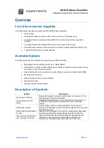
Page 6: ...eam Outlet Heating Element Connectors Controller Water Level Sensor Manual Drain Valve Water Inlet Disconnect Switch Right Side Access Door to Low Voltage Compartment Printed Circuit Board Evaporation...

Page 7: ...SKE4 E Steam Humidifier Installation Instructions and User Manual www neptronic com Page 6 Illustration 2 Overview of the Humidifier SKE4 E90 to E120...

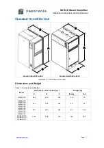
Page 8: ...s SKE4 E90 to E120 Illustration 3 SKE4 Steam Humidifier Dimensions and Weight Table 1 Dimensions and Weight Model Dimensions of the Cabinet mm Weight kg A B C Empty Full SKE4 E05 584 492 349 32 39 SKE...

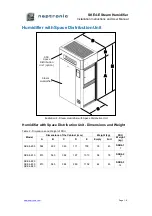
Page 9: ...umidifier with Space Distribution Unit Dimensions and Weight Table 2 Dimensions and Weight of SDU Model Dimensions of the Cabinet mm Weight kg SDU Weight kg A B C D E Empty Full SKE4 E05 584 492 349 1...

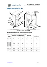
Page 10: ...A B C Alphanumeric Display Window Models SKE4 E90 to E120 Illustration 5 Weather Proof Enclosure Weather Proof Enclosure Dimensions and Weight Table 3 Weather Proof Enclosure Dimensions and Weight Mod...

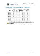
Page 11: ...KE4 E10 10 7 5 33 11 1 35 SKE4 E20 20 15 22 1 51 SKE4 E30 30 22 33 1 51 SKE4 E40 40 30 44 1 51 SKE4 E50 50 36 53 1 76 SKE4 E60 60 44 64 1 76 SKE4 E80 80 60 87 1 76 SKE4 E90 90 66 96 1 76 SKE4 E100 100...

Page 12: ...before deciding the location for the SKE4 Steam Humidifier x Plan a location that is easy to access and permits an easy inspection and servicing of the humidifier x Do not install the humidifier where...

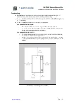
Page 13: ...he humidifier For models SKE4 E05 to E80 o Mount the humidifier at a minimum height of 0 6 m above floor level o Leave a clearance of at least 0 25 m under the humidifier for installation of water sup...

Page 14: ...or wall brick concrete stud partition wall on which the humidifier will be mounted See the Dimensions and Weight section page 7 to know the weight of the unit Illustration 7 Mounting Bracket Positioni...

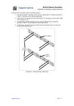
Page 15: ...g Brackets 2 Drill 4 screws not supplied into the slotted holes of the top bracket to secure the bracket to the support or wall 3 Place the bottom bracket supplied on the support or wall as per the di...

Page 16: ...ket Connection 6 Open the front door of the humidifier to gain access to the slotted holes located in the back of the cabinet Verify that the holes are aligned with the ones located in the center of t...

Page 17: ...ust be mounted such that the SDU fan section is at least 2 m above the floor x Allocate a minimum clearance of 0 45 m from the ceiling to avoid ceiling and wall condensation x If additional ventilatio...

Page 18: ...he building structure or to other expensive equipment x Maintain the following minimum clearances while installing to enable access for inspection and servicing Side Minimum Clearance Top 51 cm Both s...

Page 19: ...Manifold S A M Horizontal Duct The S A M system is suitable for installations where absorption distances are short less than 1500 mm and or low duct temperatures are in effect Illustration 13 Steam Ab...

Page 20: ...Manifold S A M or S A M E2 Vertical Duct Multi Steam System The Multi Steam system is used in critical locations in air handling systems particularly where absorption distances are very short less th...

Page 21: ...51 mm 51 mm 76 mm Illustration 17 Duct Hole Dimensions and Minimum Distance WARNING Risk of condensation Ensure that the minimum distance at the end of the manifold is at least 102 mm from the top of...

Page 22: ...e Placement Horizontal Duct 51mm Diameter Pipe 1 Pipe 2 Pipes 3 Pipes Illustration 19 51 mm Diameter Pipe Placement Horizontal Duct Note 51 mm steam pipe must be supported on the end by appropriate du...

Page 23: ...et Orientation 35 mm Diameter Pipe 1 Pipe 2 Pipes Illustration 21 35 mm Diameter Pipe Placement Vertical Duct 51 mm Diameter Pipe 1 Pipe 2 Pipes 3 Pipes Illustration 22 51 mm Diameter Pipe Placement V...

Page 24: ...where condensate can be trapped x Ensure that the slope of the steam hose rigid or flexible is not less than 15 7 horizontal lengths for 1 vertical length in order to ensure continuous drainage of co...

Page 25: ...of the steam supply piping The steam separator S trap must be installed higher than the static pressure of the system by at least 51mm Illustration 24 Steam Output Connection Incorrect Installation Il...

Page 26: ...nic com Page 25 Position of Steam Outputs Table 7 Position of Steam Outputs Model I J K SKE4 E05 171 mm 232 mm SKE4 E10 SKE4 E20 SKE4 E30 SKE4 E40 191 mm 305 mm SKE4 E50 SKE4 E60 SKE4 E80 191 mm 584 m...

Page 27: ...hose clamp supplied x Connect the condensate hose to the bottom of the SDU and to an open drain or to the humidifier using the knockout hole located on the back of the cabinet x Connect the electrical...

Page 28: ...Wall Mounting the Remote SDU A B C 4 102mm D E Illustration 27 Remote SDU Mounting Bracket Table 8 Remote SDU Mounting Bracket Dimensions Model SDU Dimensions mm A B C D E SKE4 E05 SDU4 1 406 171 348...

Page 29: ...the optional remote SDU cover 1 Secure the two side covers onto the remote SDU mounting bracket by fastening them with 3x M3 5 x 0 6 nuts supplied 2 Secure the front cover onto the remote SDU mounting...

Page 30: ...r x As the humidifier is equipped with the Neptronic Anti Foaming Energy Conservation AFEC system which drains the humidifier in the presence of foam to ensure clean and safe operation the use of soft...

Page 31: ...KE4 E90 to E120 Model Dimensions mm A B C D SKE4 E90 SKE4 E100 SKE4 E110 SKE4 E120 105 340 489 25 Note For models SKE4 E90 to E120 the water supply inlet and main drain outlet are located on the right...

Page 32: ...of the pipe x In order to facilitate servicing install a shutoff valve not supplied in the water supply line close to the humidifier x It is recommended to install a standard water strainer in the wat...

Page 33: ...ration 31 Water Supply and Drain Connections x Use DN20 and DN15 standard copper or stainless steel hydraulic pipes x It is recommended that the installed drain piping is rated for 100 C x Ensure that...

Page 34: ...Inlet NPT DN15 Pan Drain DN22 Steam Outlet Models SKE4 E90 to E120 Illustration 34 Weather Proof Enclosure Plumbing Side View Note By default the steam outlet water supply inlet and main drain outlet...

Page 35: ...switch to turn off the power without opening any access doors x An external over current protection must be installed on the supply adjacent to the humidifier It is also recommended to install a circu...

Page 36: ...t Holes Models SKE4 E05 to E80 Power Supply Knockout Hole Models SKE4 E90 to E120 Illustration 36 Power Supply Holes Standard Humidifier For humidifiers having the weather proof enclosure designated p...

Page 37: ...D card port TXD RXD TXD RXD CN2 USB drive port 4 LCD1 1 2 WATER LEAK DETECT TB7 4 5 JP3 JP4 JP5 ETHERNET BOARD ETHERNET BOARD NETWORK BOARD 1 2 1 2 1 2 1 2 1 2 3 4 1 2 3 4 1 2 3 4 1 2 3 ETHERNET PCB N...

Page 38: ...en but will not generate an alarm If an airflow switch is not used install a jumper between terminals TB3 1 2 The High limit humidistat contact must be wired between terminals TB3 1 3 If this contact...

Page 39: ...ommon Normally Open Normally Closed Common 1 2 1 2 1 2 3 4 5 1 2 3 4 5 6 1 2 3 1 Illustration 40 Alarm and Service Contact Wiring ON OFF Humidifier For operation of On Off humidifiers connect the On O...

Page 40: ...umidifiers the analog signal s must be connected between terminals TB4 1 and TB4 3 4 and or 5 To configure the source of the signal s access the Control sub menu located in the Installation menu see p...

Page 41: ...0 humidistat with SHR10 or SHC80 as space sensor Illustration 43 Control Signal from HRO20 Humidistat with Remote Humidity Sensor SHR10 or SHC80 Humidity Control by Humidifier Internal Mode Humidity c...

Page 42: ...er Installation Instructions and User Manual www neptronic com Page 41 Humidity Control by External Signal Humidity controlled externally using an external signal source Illustration 45 Control Signal...

Page 43: ...als TB1 1 2 to the network RS485 A B The network control signal s must be selected by accessing the Control sub menu located in the Installation menu see page 52 To setup the communication parameters...

Page 44: ...ly ducts or sources of heat or cold x The airflow switch must be placed in a position capable of accurately opening on a loss of air flow in order to prevent the humidifier from running when there is...

Page 45: ...ven when the humidifier is powered off the controller remains operational Drain Button The drain button is used to manually activate the drain cycle Must be pressed and held for 3 seconds to perform t...

Page 46: ...ion 49 Idle Screen Display Menu Access x From the Idle Screen the Main Menu can be accessed by pressing the Back Menu button enabling access to the General menu x To view other menu options and perfor...

Page 47: ...egory and press Enter to advance to the next sub menu B Use the and b c ea e a d dec ea e a e U e he b c the next or previous parameter Values are saved as soon as a change is made C Press the Back Me...

Page 48: ...ier WtrProbeFail None None Capacitive Resistive Both Displays which one of the water level sensor probes is currently not functioning properly Control RoomDemand Current value min 0 00 max 100 00 Disp...

Page 49: ...ectric current in the second current sensor Only appears when using two current sensors ContactorsFuse Normal Normal Blown Fuse Displays the current status of the PCB fuse If Blown Fuse is displayed t...

Page 50: ...rent application software version SerialNo Displays the serial number of the humidifier Profile Displays a short profile for the configured device MCULoad Current value min 0 0 max 100 0 Displays the...

Page 51: ...yHLStp 80 00 min 0 00 max 100 00 Define the supply high limit demand setpoint value System UTCOffset 300min min 720min max 720min Configure the value of the UTC offset DaylightSavings No No Yes Select...

Page 52: ...lays the runtime of the unit since the last servicing ServOnTime 0 00hr Displays the operating time of the unit since the last servicing ServiceDue Off Off On Displays whether the humidifier is due fo...

Page 53: ...Only appears if ControlProfile is set to an internal control mode or HumCntrlDemandSrc is set to RoomDemand RoomRHSrc None None RoomRH Network Select the reading source for the room demand Network op...

Page 54: ...plicable for humidifiers having the SDU option MinSteamOut 5 min 1 max 25 Set the minimum steam production demand value below which no steam will be produced DrainInterval 6hr min 0hr max 24hr Set the...

Page 55: ...s performed configure the value of the IdleRinseInterval setting IdleRinseOff Off Off On Select whether to enable automatic rinse cycles while the humidifier is turned off and remains inactive To sele...

Page 56: ...imperial system of units for the BACnet server BACnetMSTP 10 Only appears if NtwrkOption is set to BACnet MaxMaster 127 min 1 max 127 Configure MaxMaster value to increase network efficiency when the...

Page 57: ...ort 502 min 0 max 65535 Set the communication port number Modbus TCP port number is set by default SMTP 7 SSL Off Off On If turned to On a secure socket layer will be used to encrypt the communication...

Page 58: ...ffective StaticAddress 192 168 1 100 Configure the static IP address StaticSubnetMask 255 255 255 0 Configure the static subnet mask StaticDefaultGateway 192 168 0 100 Configure the static default gat...

Page 59: ...has been detected but it is not operating correctly or is non functional Verify the SD card and replace if defective Automatic Foam Warning If Detected is displayed it indicates that the foam sensor h...

Page 60: ...rs having the BACnet or Modbus option Manual HRLState Indicates that there is a communication error when attempting to connect to the HRL24 controller Verify the wiring between the humidifier and the...

Page 61: ...connected with a pitch of at least 6 5mm per 300mm horizontal run Steam 7 Verify that the steam distributors are properly installed into the ventilation duct or that the SDU is properly installed and...

Page 62: ...ration chamber by using the control panel to access the WaterLevel setting located in the Physical IO sub menu of the General menu Ensure that there are no water leaks along the water line f Once the...

Page 63: ...ves the following steps Stage 1 Drain the Evaporation Chamber Stage 2 Shut Down the Electrical Supply Stage 3 Remove Additional Water Residue Stage 4 Remove and Clean the Evaporation Chamber Stage 5 R...

Page 64: ...is sufficiently cool remove the power supply to the humidifier at the disconnect switch or the breaker Stage 3 Remove Additional Water Residue 1 Remove the plumbing compartment access panel and turn...

Page 65: ...front of the evaporation chamber by removing the safety pins and manually disconnecting the hose shank coupling from the plumbing section of the humidifier Connect and secure the water plug to the inl...

Page 66: ...ntain a few inches of water Ensure that your footing is secure when removing the chamber Take extra precautions when removing the evaporation chamber from large humidifiers which may feel heavy when b...

Page 67: ...rforming a drain cycle using the Drain button 4 Restart the humidifier to resume normal operation by pressing and holding the Power button for 3 seconds 5 To reset the service counters and clear the a...

Page 68: ...the water supply line is open Verify the operation of the fill valve Check that the fill valve strainer and the external strainer are not blocked Humidifier is not being filled with water Humidifier d...

Page 69: ...Steam Humidifier Installation Instructions and User Manual www neptronic com Page 68 Exploded View and Bill of Material Exploded View SKE4 Cabinet SDU Cabinet Optional Illustration 52 Exploded View P...

Page 70: ...SKE4 E Steam Humidifier Installation Instructions and User Manual www neptronic com Page 69 Electrical Compartment Plumbing Compartment Illustration 53 Exploded View Part 2...

Page 71: ...ature switch klixon SKE4 E05 to SKE4 E120 SP 3036 9 Foam sensor SKE4 E05 SW FOAMSM ASSY SKE4 E10 to SKE4 E80 SW FOAMMED ASSY SKE4 E90 to SKE4 E120 SW FOAMSM ASSY 10 Water level sensor See table below...

Page 72: ...AD DP13 3004 SP 3374 SP 3080 SP 3393 SKE4 E30 400V 3 SW 5983 3x SW SK4TEMPSENS 12 SW SK4WLTR2 HEAD DP13 3005 SP 3374 SP 3100 SP 3393 SKE4 E40 400V 3 SW 5955 3x SW SK4TEMPSENS 12 SW SK4WLTR2 HEAD DP13...

Page 73: ...Notes...

Page 74: ......

Page 75: ......

Page 76: ...u blvd Montreal Qc H4N 1R6 Canada www neptronic com Toll free in North America 1 800 361 2308 Tel 514 333 1433 Fax 514 333 3163 Customer service fax 514 333 1091 Monday to Friday 8 00am to 5 00pm East...

Reviews: