SKE4-E Steam Humidifier
Installation Instructions and User Manual
Page | - 20 -
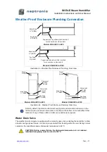
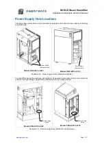
Positioning S.A.M. and S.A.M.E2
Duct Mounting
The steam manifold must be mounted and secured through the side of the air handling unit or duct.
Ensure that provisions are made for safe accessibility, ideally with an observation light and window.
Ensure that the construction of the duct wall is suitable enough to support the steam pipe for the duration
of the installation life.
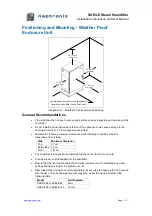
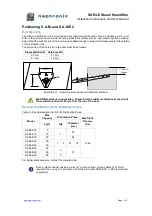
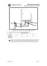
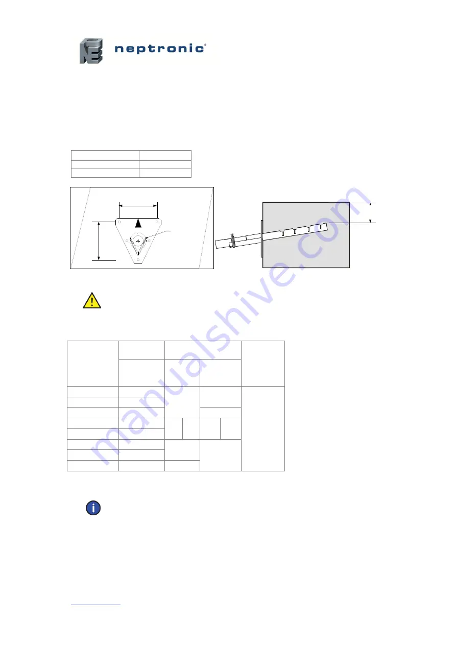
The dimension of the hole size in the duct must be as follows:
Steam Manifold Ø Hole Size ØA
35 mm
51 mm
51 mm
76 mm
Illustration 17 - Duct Hole Dimensions and Minimum Distance
WARNING: Risk of condensation. Ensure that the minimum distance at the end of
the manifold is at least 102 mm from the top of the duct.
Recommendation for S.A.M. Distribution Pipes
Table 6 - Recommendation for S.A.M. Distribution Pipes
Model
Max
Capacity
Distribution Pipes
Max Static
Pressure
(Pa)
kg/hr
Qty
Diameter
(mm)
SKE4-E05
5
1
35
1245
SKE4-E10
10
SKE4-E20
20
54
SKE4-E30
30
1
2
51
35
SKE4-E40
40
SKE4-E50
50
2
51
SKE4-E60
60
SKE4-E80
80
3
For higher static pressure, contact the manufacturer.
Note: A steam header having an inlet of 76 mm and two or three outlets of 51 mm is
required when using S.A.M. steam manifolds for models SKE4-E50 to E80 (purchased
seperately).
5'
(120mm)
5
'
(1
2
0m
m
)
ØA
4'
(102mm)

