SKE4-E Steam Humidifier
Installation Instructions and User Manual
Page | - 37 -
T
B
4
T
B
3
T
B
2
T
B
5
T
B
6
Airflow switch
High limit humidistat
Interlock
On/Off demand contact
Alarm Contacts
Service Contacts
Control Demand
Room Humidity
Duct Humidity
Steam Output
Common
24 Vac
A+
B-
24 Vac
T
B
1
A+
B-
RS 485
(HRL24)
Electrical Control
Connections
Common
Normally Open
Normally Closed
Common
Normally Open
Normally Closed
1
2
1
2
1
2
3
4
5
1
2
3
4
5
6
1
2
3
1
2
3
Power Output
Analog Inputs
Analog Output
Safety Contacts
Network Contacts
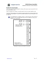
RS 485
(BACnet MS/TP
or Modbus RTU)
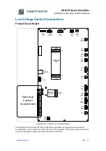
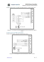
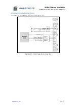
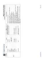
Illustration 39 - Electrical Control Connections
Safety Contact Connections
The
Airflow switch
contact must be wired between terminals TB3 1&2. If this contact opens,
operation of the SKE4 unit will stop. The unit will display the airflow switch as open, but will not
generate an alarm. If an airflow switch is not used, install a jumper between terminals TB3 1&2.
The
High limit humidistat
contact must be wired between terminals TB3 1&3. If this contact opens,
operation of the SKE4 unit will stop and an
alarm
message will be displayed. If a high limit humidistat
is not used, install a jumper between terminals TB3 1&3.
The
Interlock
must be wired between terminals TB3 1&4. If this contact opens, operation of the SKE4
unit will stop. The unit will display the Interlock as open, but will not generate an alarm. If Interlock is
not used, install a jumper between terminals TB3 1&4.
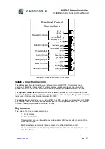
Dry Contacts
Two series of volt free contacts are provided:
1. Alarm Contacts
2. Service Contacts
x
These contacts are used to switch a low voltage, ideally 24V, with a switching current of no
more than 3 Amps.
x
Each series has one Normally Closed contact and one Normally Open contact.
x
It is recommended to use the Normally Closed contact, as this contact will open in the event
of a humidifier fault.

