background image


SKG3 Gas Fired Humidifier 

Installation Instructions and User Manual


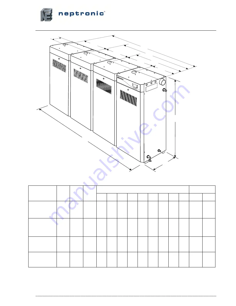
Dimensions & Weights 


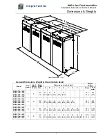
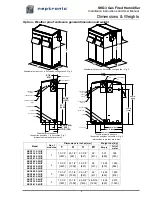
General dimensions - Fig. 2


General Dimensions, Weight & Steam Outlets detail 

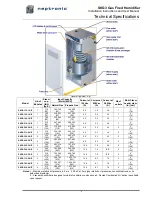
Model 

Nb of 

module 

No of 

Steam 

Outlets 

Steam  

Outlet  

Diam. 

Dimensions in inches [mm] 

Weight  

Lb (Kg) 

Empty 

Full of 

water 

SKG3-110-1 N/P 
SKG3-155-1 N/P 
SKG3-180-1 N/P 
SKG3-210-1 N/P 

Ø

3” 

[76] 

54 

[1372] 

24 

[610] 

22 

[560] 

[230] 

18 

[460] 


320 

[145] 

444 

[200] 

SKG3-265-2 N/P 
SKG3-310-2 N/P 
SKG3-350-2 N/P 
SKG3-405-2 N/P 

Ø

3” 

[76] 

54 

[1372] 

48 

[1220] 

22 

[560] 

[230] 

18 

[460] 

24 

[610] 

36 

[920] 


602 

[274] 

850 

[384] 

SKG3-505-3 N/P 
SKG3-560-3 N/P 
SKG3-610-3 N/P 

Ø

3” 

[76] 

54 

[1372] 

72 

1830] 

22 

[560] 

[230] 

18 

[460] 

24 

[610] 

36 

[920] 

66 

[1680] 


950 

[431] 

1,322 

[600] 

SKG3-710-4 N/P 
SKG3-765-4 N/P 
SKG3-810-4 N/P 

Ø

3” 

[76] 

54 

[1372] 

96 

[2440] 

22 

[560] 

[230] 

18 

[460] 

24 

[610] 

36 

[920] 

66 

[1680] 

90 

[2290] 

1,270 

[576] 

1,766 

[800] 


B

A

C

E

F

F

F

D

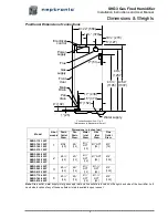
G

H

I

Summary of Contents for SKG3-110-1 N/P

Page 1: ...nce WHAT TO DO IF YOU SMELL GAS Do not try to light any appliance Do not touch any electrical switch and do not use telephones in your building Immediately call your gas supplier from an off site tele...

Page 2: ...ocal regulations concerning the provision of electrical installations are followed HEALTH SAFETY Neptronic has considered aspects of the design of their humidification systems to reduce as much as pos...

Page 3: ...ation of these instructions will ensure the conformity of your installation and operation as per the manufacturer s recommendations The application of these instructions is one of the conditions for t...

Page 4: ...on 28 Stage 8 Electrical Supply and Installation 30 Stage 9 Electrical Control Connections 31 Stage 9 BACnet Interface Set up 34 Initial Verification 35 Commissioning Operation Description 37 Operatio...

Page 5: ...104 123 463 104 136 9 0 5 2 4 5 2 4 100 SKG3 350 2 N P 2 350 160 457 475 134 500 475 147 9 0 5 2 4 5 2 4 100 SKG3 405 2 N P 2 405 185 494 846 145 537 846 158 9 0 5 2 4 5 2 4 100 SKG3 505 3 N P 3 505...

Page 6: ...P SKG3 180 1 N P SKG3 210 1 N P 1 1 3 76 54 1372 24 610 22 560 9 230 18 460 320 145 444 200 SKG3 265 2 N P SKG3 310 2 N P SKG3 350 2 N P SKG3 405 2 N P 2 2 3 76 54 1372 48 1220 22 560 9 230 18 460 24...

Page 7: ...3 310 2 N P SKG3 350 2 N P SKG3 405 2 N P 2 1 40 15 NPT 15 1 NPT 25 4 100 SKG3 505 3 N P SKG3 560 3 N P SKG3 610 3 N P 3 1 40 15 NPT 15 1 NPT 40 5 125 SKG3 710 4 N P SKG3 765 4 N P SKG3 810 4 N P 4 1...

Page 8: ...inches mm Air inlet Diam J K L M N O SKG3 110 1 N P SKG3 155 1 N P SKG3 180 1 N P SKG3 210 1 N P 1 1 2 51 17 6 448 13 8 352 SKG3 265 2 N P SKG3 310 2 N P SKG3 350 2 N P SKG3 405 2 N P 2 2 2 51 17 6 44...

Page 9: ...73 1 2 1867 25 1 2 647 33 1 8 841 24 611 627 285 748 340 SKG3 265 2 N P SKG3 310 2 N P SKG3 350 2 N P SKG3 405 2 N P 2 73 1 2 1867 51 1 2 1308 33 1 8 841 24 611 1 038 472 1 280 582 SKG3 505 3 N P SKG3...

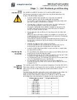
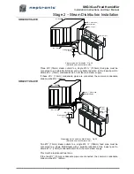
Page 10: ...to ensure balanced load before lifting Lifting of SKG3 Steam Humidifier MUST ALWAYS be done using the appropriate Neptronic Lifting Bracket sold separately Lifting sling angle must be greater than 30...

Page 11: ...tability To install the SKG3 Steam Humidifier and its associated components no special tooling is required above that of a fitter s toolkit Installation Method Statement Stage1 Unit Positioning and Mo...

Page 12: ...ocate the humidifier as close as possible to an outside wall or roof to ensure that the flue pipe from the humidifier is short and direct Locate the SKGE3 Steam Humidifier on a water proof floor or in...

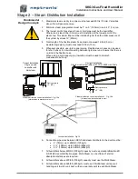
Page 13: ...510mm and 29 9 762mm The humidifier is designed to be installed directly on the floor Provide a level solid foundation for the humidifier Ensure that the floor beneath the humidifier is water proof to...

Page 14: ...in the flexible hose When using a rigid copper pipe insulation must be used to diminish condensation build up Min 7 Correct Installation Single module humidifier with Multisteam Static pressure 2 50 S...

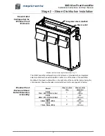
Page 15: ...h an outlet located on either one of the sides of the humidifier By default the steam outlet will be on the right side of the humidifier when facing the control panel Steam outlet side can be switched...

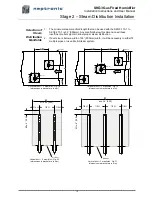
Page 16: ...of 35 900mm width it will be necessary to either fit multiple pipes or use a Multi Steam system Horizontal duct 2 manifolds Fig 18 dimensions in bracket are in mm Horizontal duct 3 manifolds Fig 19 d...

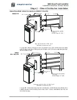
Page 17: ...3 76mm feed pipe must be connected to two 2 S A M E2 steam manifolds with a suitable reduction at the lowest point to allow a 15mm condensate drain from the main steam supply SKG3 155 180 210 Min 7 p...

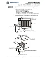
Page 18: ...y can be placed side by side 3 For installation of Multi Steam units please refer to Neptronic Multi Steam Installation Instructions Multi Steam in Horizontal duct Fig 24 dimensions in bracket are in...

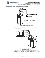
Page 19: ...15mm condensate drain from the main steam supply SKG3 265 to 405 Steam pipe work 2 modules Multi Steam Fig 27 dimensions in bracket are in mm Two 3 76mm steam outlets to a single 4 108mm feed pipe mu...

Page 20: ...n condensate drain must be 22mm SKG3 710 to 810 Steam pipe work 4 modules Multi Steam Fig 29 dimensions in bracket are in mm Two 3 76mm steam outlets to a single 4 108mm feed pipe must be connected to...

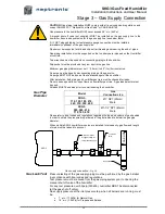
Page 21: ...field piping and humidifier gas train must be checked for leaks Do not use soap solution or open flame on humidifier gas train A gas leak detector must be used All leaks MUST be sealed prior to commi...

Page 22: ...supply pressure 10 to 70psig 70 to 480kPa Minimum water temperature 49 F 4 C Maximum water temperature 104 F 40 C Model Water inlet Connection size SKG3 110 to 810 1 2 NPT 15mm Male Water Supply Line...

Page 23: ...onnection must be connected to drain pipe through separated line Drain connection Fig 32 Pan Drain Connection on Weather Proof Enclosure Weather proof enclosure is provided with a pan drain at the bas...

Page 24: ...r supply must be provided for the ventilation devices in addition to that required by the humidifier Any installation work must be carried out by suitably qualified personnel With the exception of duc...

Page 25: ...2 N P 2 160 960 160 960 SKG3 505 3 N P 3 180 1080 180 1080 SKG3 560 3 N P 3 200 1200 200 1200 SKG3 610 3 N P 3 240 1440 240 1440 SKG3 710 4 N P 4 280 1680 280 1680 SKG3 765 4 N P 4 300 1800 300 1800...

Page 26: ...he number of turns or elbows with a maximum of 6 elbows in total Use only duct materials suitable to supply air from the outside to the humidifier Combustion air duct length and flue gases venting pip...

Page 27: ...110 to 210 Ducted combustion air 1 module Fig 35 dimensions in bracket are in mm 2 Modules Humidifier SKG3 265 to 405 Ducted combustion air Fig 36 dimensions in bracket are in mm Combustion air 2 51...

Page 28: ...37 dimensions in bracket are in mm 4 Modules Humidifier SKG3 710 to 810 Ducted combustion air Fig 38 dimensions in bracket are in mm Combustion air from outside Flue gases Humidifier inlet 2 51 2 51 m...

Page 29: ...vent pipe must be insulated in order to reduce the formation of condensate Approved BH vent systems Cheminee Lining HEP HEPL or HEPL2 rigid venting system Flexmaster Z Vent Model SVE Series III rigid...

Page 30: ...w beside or facing any electric or gas meter regulator or relief device When flue gas terminal is located in car port in residential building Minimum spacing in mm Building or other element 8 200 Belo...

Page 31: ...fier The isolator must have a contact separation of at least 1 8 3mm Electrical connection All work related to electrical installation MUST only be performed by skilled and qualified technical personn...

Page 32: ...rm message will be displayed A third interlock switch can be wired between terminals TB1 2 5 If this contact is open operation of humidifier will stop and an Alarm message will be displayed TB1 Interl...

Page 33: ...Signal H R O 2 0 1 3 2 4 5 6 7 8 9 1 2 3 4 5 6 1 2 3 R R LAST ANLG OUT 1 2 3 4 5 X 6 7 8 9 DUCT HUMID ROOM HUMID CTRL DEMAND INTER LOCK PD SW ITCH HI LIM 24 VAC 700MA MAX TB1 TB2 JP2 JP1 DS1 O N P1 R...

Page 34: ...rol up to 24Vac or Vdc with a switching current of no more than 3 A Operation Alarm contact wiring Fig 46 Common 24 VAC RH Control Signal H R O 2 0 Common 24 VAC RH S H C 8 0 1 3 2 4 5 6 7 8 9 1 2 3 4...

Page 35: ...Baud rate selection Baud rate Switch 2 Switch 3 9600 OFF OFF 19200 ON OFF 38400 OFF ON 76800 factory setting ON ON See also the BACnet communication module user guide supplied 1 3 2 4 5 6 7 8 9 1 2 3...

Page 36: ...Once the shut off valve is turned ON check for leaks gas smell or hissing sounds Flue Gases Venting 10 Verify the flue gases venting as follows a A tee is installed with a drain tee cap for the conden...

Page 37: ...a cold water start the humidifier will require 5 to 10 minutes to produce steam The Humidifier LCD display will indicate water temperature and flue gases temperature g During normal operation while s...

Page 38: ...trol Set up 3 System Set up 4 Alarms 5 Diagnostics 6 Com Set up Use the or buttons to scroll up or down and access a menu by pressing the button Within a menu press on the or buttons to pass from one...

Page 39: ...been flushed of the remaining water in order to prevent growth of bacteria Upon new humidity demand evaporation chamber s will fill up with fresh water and produce steam INPUT SUPPLY TOO LOW Voltage...

Page 40: ...be for each module Value is indicated in 100 indicate that the evaporation chamber is full of water During normal operation the value can fluctuate between 95 and 105 Water Temperature Displays the wa...

Page 41: ...oltage or Amp From 0 to 10 V or 2 to 10 V Or 4 to 20 mA Room RH Source Selection of room relative humidity source External Com Port Humidity Input Setup Selection of humidity input Voltage or Amp From...

Page 42: ...Gain Selection of PID control gain values KP from 0 to 100 KI from 0 to 100 KD from 0 to 100 Tank Operation Selection of tank operation when SKG3 humidifier has more than one module For optimum humidi...

Page 43: ...setting is enabled From 50 to 90 C or OFF Increment 5 C Default OFF Anti Freeze Temperature Selection of evaporation chamber anti freeze temperature If enabled combustion will be ordered to maintain w...

Page 44: ...is indicated in relative number From 140 to 180 Increment 1 Default 160 Language Selection Selection of the language displayed by interactive menus English or Fran ais Default English Time Date Setup...

Page 45: ...0 seconds Value is indicated in Hours Alarms for Unit 1 Displays alarm s message s for module 1 whenever necessary Alarms for Unit 2 Displays alarm s message s for module 2 whenever necessary Alarms f...

Page 46: ...will fire up the burner to heat the water This alarm will reset automatically when the water temperature reaches the proper value Water Temp too high Water temperature is above the pre set maximum va...

Page 47: ...speed sensor for each module Value is indicated in Hz DIAGNOSTICS 504 Burner Gas Valve H1 OFF H2 OFF H3 OFF H4 OFF Burner Gas Valve Displays the state of the burner gas valve Value indicated is On or...

Page 48: ...o1 at the ON position Configuration mode see the Stage 9 BACnet Interface Set up section of the manual From 0 to 255 Increment 1 Default 0 Device Instance Selection of device instance value This value...

Page 49: ...SKG3 Gas Fired Humidifier Installation Instructions and User Manual 48 Personal Notes...

Page 50: ...3380 208 24Vac 100VA All models SP 3308 230 24Vac 100VA All models SP 3310 9 Combustion blower gas valve assembly See detail 10 Combustion blower gasket All models SP G2104 11 Igniter holder assembly...

Page 51: ...bustion component detail table 27 Burner assembly See combustion component detail table 28 Burner assembly gasket All models SP G2111 29 Water temperature sensor All models SW GWATTEMP ASSY 30 AFEC pr...

Page 52: ...er and gas valve assembly Fig 53 Combustion component detail table Item Description Part number by Module type Module SKG 100 Module SKG 150 Module SKG 180 Module SKG 200 26 Heat Exchanger SW GTANKCOV...

Page 53: ...208 or 240V SW GIGNITER 230 Item 14 Internal flue pipe SKG3 505 to 810 Flue pipe assembly Fig 55 Item Description Model Part number 47 Flue section SKG3 505 to 810 SP G2201 48 Flue breech pipe gasket...

Page 54: ...nd User Manual 53 Exploded Views Parts List Water level sensor assembly Water level sensor assembly Fig 56 Item Description Model Part number 53 Water level sensor assembly All models SW GWATLEV ASSY...

Page 55: ...SKG150 SKG180 SKG200 SKG3 110 1 N P 1 x1 SKG3 155 1 N P 1 x1 SKG3 180 1 N P 1 x1 SKG3 210 1 N P 1 x1 SKG3 265 2 N P 2 x1 x1 SKG3 310 2 N P 2 x2 SKG3 350 2 N P 2 x1 x1 SKG3 405 2 N P 2 x2 SKG3 505 3 N...

Page 56: ...u blvd Montreal Qc H4N 1R6 Canada www neptronic com Toll free in North America 1 800 361 2308 Tel 514 333 1433 Fax 514 333 3163 Customer service fax 514 333 1091 Monday to Friday 8 00am to 5 00pm East...

Reviews: