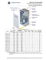
SKG3 Gas Fired Humidifier
Installation Instructions and User Manual
6
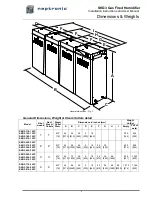
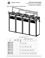
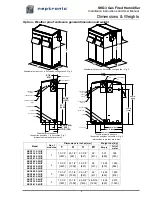
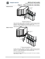
Dimensions & Weights
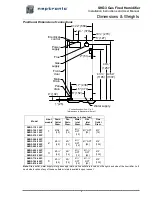
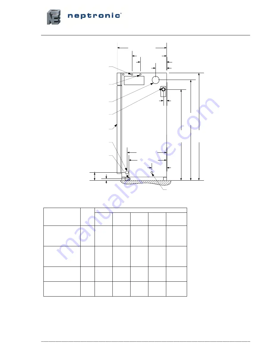
Position & Dimension of connections
Connections position - Fig. 3
(dimensions in bracket are in mm)
Model
Nb of
module
Dimensions in inches [mm]
Drain
Outlet
Diam.
Pan
Drain
Diam.
Water
Inlet
Diam.
Gas
Inlet
Diam.
Flue
Outlet
Diam.
SKG3-110-1 N/P
SKG3-155-1 N/P
SKG3-180-1 N/P
SKG3-210-1 N/P
1
Ø3/4’’
[20]
ؽ”
[15]
ؽ”
NPT
[15]
Ø1” NPT
[25]
Ø3”
[76]
SKG3-265-2 N/P
SKG3-310-2 N/P
SKG3-350-2 N/P
SKG3-405-2 N/P
2
Ø1-
½”
[40]
ؽ”
[15]
ؽ”
NPT
[15]
Ø1” NPT
[25]
Ø4”
[100]
SKG3-505-3 N/P
SKG3-560-3 N/P
SKG3-610-3 N/P
3
Ø1-½
”
[40]
ؽ
”
[15]
ؽ
”
NPT
[15]
Ø1-½
”
NPT
[40]
Ø
5”
[125]
SKG3-710-4 N/P
SKG3-765-4 N/P
SKG3-810-4 N/P
4
Ø1-½
”
[40]
ؽ
”
[15]
ؽ
”
NPT
[15]
Ø1-½
”
NPT
[40]
Ø
5”
[125]
Note
: Drain outlet, water supply inlet, gas supply inlet and flue outlet are located on the right hand side of the humidifier. Left
hand side location of any of these outlets or inlets is available upon request.
14
½’’ (370)
C=22'
’ (560)
2'
’ (51)
6'
’ (152)
17'
’ (436)
15'
’ (378)
4'
’ (102)
43
½’’
(1105)
49
½’’
(1257)
A=54'
’
(1372)
1'
’ (25)
Electrical
control
Power
supply
Flue
Gas
supply
Front
door
Main
Drain
Pan
drain
5'
’ (127)
Water supply
10
½’’ (270)

