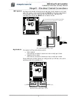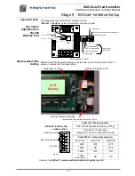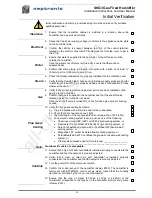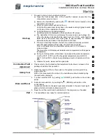
SKG3 Gas Fired Humidifier
Installation Instructions and User Manual
29
Stage 7
– Flue Gas Venting Connection
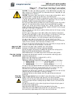
Minimum
Spacing
When flue gas terminal is located in outside air:
Minimum spacing
(in) [mm]
Building or other element
12 [300]
Below adjacent opening (window, air vent or any
other ventilation opening)
3 [75]
Below a gutter, drain or soil pipe
8 [200]
Below eaves catch or, balcony
3 [75]
Beside vertical drain or soil pipe
12 [300]
Beside adjacent corner or other flue gas terminal
6 [150]
Beside adjacent opening (door, window, air vent or
any other ventilation opening)
12 [300]
Above adjacent ground or balcony level
84 [2100]
Above ground level, in areas accessible to public
60 [1500]
Above or below other flue gas terminal
24 [600]
From a surface facing the terminal
48 [1200]
From a facing other flue gas terminal.
50 [1250]
Above, below, beside or facing any electric or gas
meter, regulator or relief device.
When flue gas terminal is located in car port in residential building:
Minimum spacing
(in) [mm]
Building or other element
8 [200]
Below car port ceiling
3 [75]
Beside vertical drain or soil pipe
12 [300]
Beside adjacent corner or other flue gas terminal
48 [1200]
Beside adjacent opening (door or window)
12 [300]
Above adjacent ground or balcony level
84 [2100]
Above ground level, in areas accessible to public
60 [1500]
Above or below other flue gas terminal
24 [600]
From a surface facing the terminal
48 [1200]
From a facing other flue gas terminal.
50 [1250]
Above, below, beside or facing any electric or gas
meter, regulator or relief device.
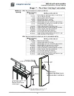
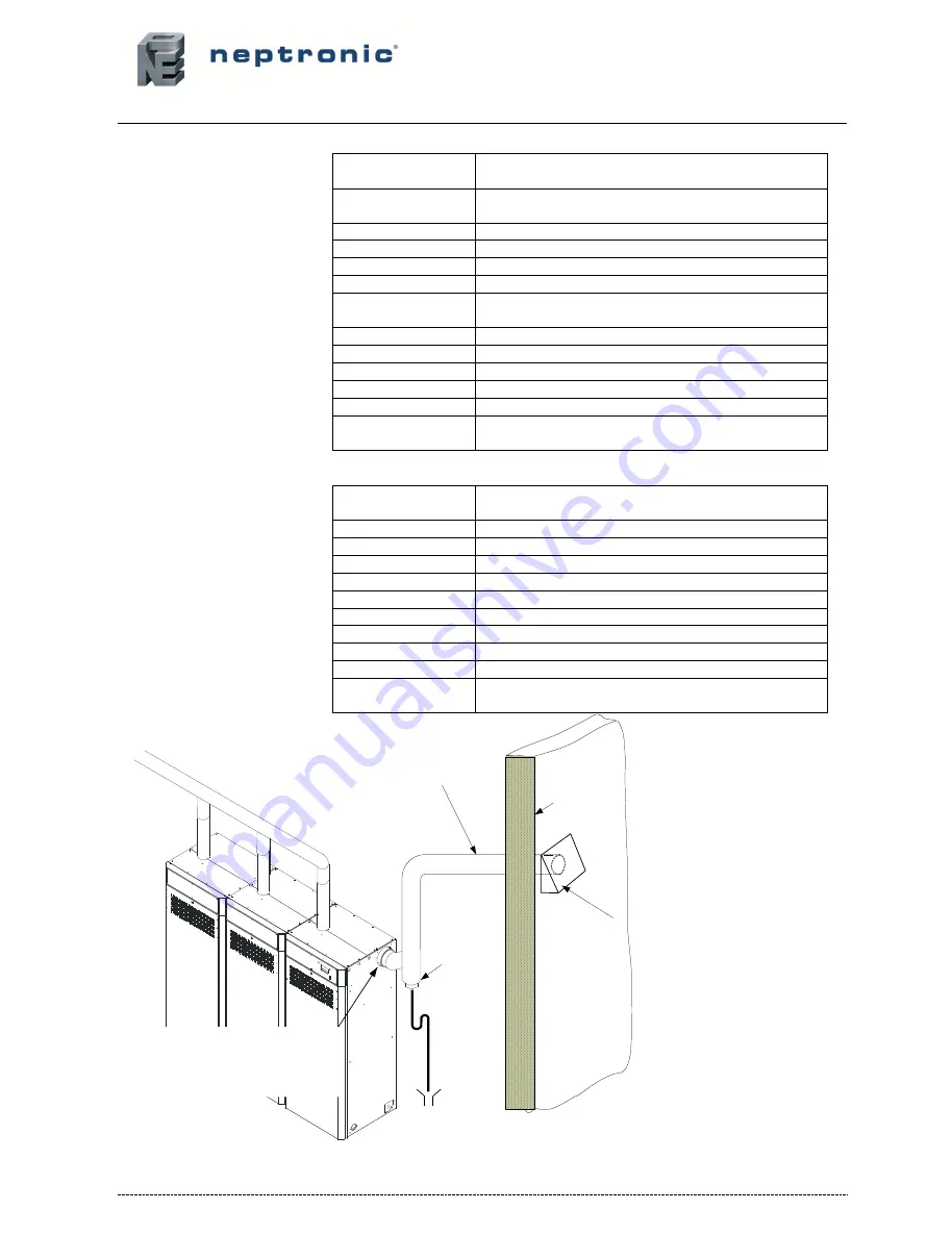
Typical flue gas installation, 3 modules - Fig. 39
(dimensions in bracket are in mm)
Ste
am
Outside wall
Flue gas venting pipe
(minimum 2% upward grandient)
Vent terminal
to prevent backflow due to
outside weather conditions
Humidifier single flue gases outlet
Ø5'
’ (125) O.D. round
Important: This connection
must be airtight
Drip trap
All manuals and user guides at all-guides.com

