SKG3 Gas Fired Humidifier
Installation Instructions and User Manual
33
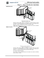
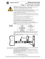
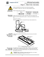
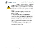
Stage 9
– Electrical Control Connections
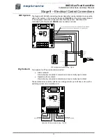
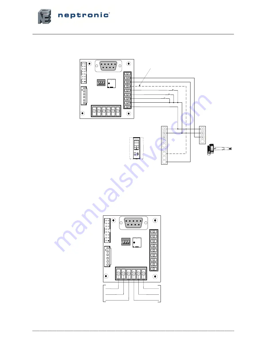
VAV System
The Neptronic® SKGE3 modulating Steam Humidifier can be installed in conjunction
with a VAV system, in this case the Neptronic®
SHC80
duct humidity sensor placed
in the supply air will act as a high level duct humidity sensor. Humidity will be
controlled by the Neptronic®
HRO20
room humidity controller.
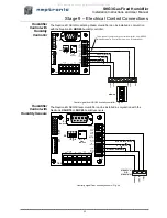
VAV configuration typical wiring - Fig. 45
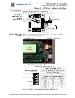
Dry Contacts
Two series of volt free contacts are provided :
Alarm contacts:
One normally connected to common and one normally open contact.
Operation (fan) contacts:
One normally connected to common and one normally open contact.
These contacts are used to switch a low voltage control, up to 24Vac or Vdc, with a
switching current of no more than 3 A.
Operation & Alarm contact wiring - Fig. 46
C o m m o n
2 4 V A C
% R H
C o n tro l S ig n a l
H R O 2 0
C o m m o n
2 4 V A C
% R H
S H C 8 0
1
3
2
4
5
6
7
8
9
1
2
3
4
5
6
1 2 3
R
-
R
+
L
A
S
T
A N L G O U T
1
2
3
4
5
X
6
7
8
9
D U C T
H U M ID .
R O O M
H U M ID .
C T R L
D E M A N D
IN T E R
L O C K
P D
S W IT C H
H I-L IM
2 4 V A C
7 0 0 M A
M A X .
T B 1
T B 2
J
P
2
J
P
1
D S 1
O
N
P 1
R S -2 3 2
A
+
B
-
T B 3
R S -4 8 5
C O M
N O
N C
C O M
N O
N C
A L A R M
F A N
T o b e w ire d if yo u in te n d to co n tro l H u m id ifie r fro m H R O 2 0
(M o d e E xte rn a l in C o n tro l S e tu p m e n u - D isp la y # 2 0 0 )
HI LEVEL HUMIDISTAT
P . D . S W IT C H
O T H E R IN T E R L O C K
1
3
1
4
1
5
1
6
1
3
2
4
5
6
7
8
9
1
2
3
4
5
6
1 2 3
R
-
R
+
L
A
S
T
ANLG OUT
1
2
3
4
5
X
6
7
8
9
DUCT
HUMID.
ROOM
HUMID.
CTRL
DEMAND
INTER
LOCK
PD
SWITCH
HI-LIM
24 VAC
700MA
MAX.
TB1
TB2
J
P
2
J
P
1
DS1
O
N
P1
RS-232
A
+
B
-
TB3
RS-485
Common
Common
Normally Closed
Normally Open
Normally Closed
Normally Open
Contact A
Alarm Contacts
Contact B
Operation Contacts
COM
NO
NC
COM
NO
NC
ALARM
FAN
All manuals and user guides at all-guides.com

