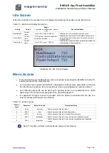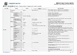
SKG4-E Gas Fired Humidifier
Installation Instructions and User Manual
Page | - 42 -
T
B
4
T
B
3
T
B
2
T
B
5
T
B
6
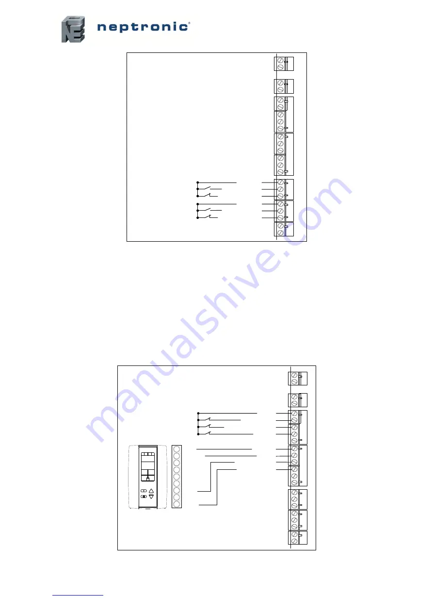
Alarm contacts
Service contacts
T
B
1
Common
Normally Open
Normally Closed
Common
Normally Open
Normally Closed
1
2
1
2
1
2
3
4
5
1
2
3
4
5
6
1
2
3
1
2
3
T
B
7
1
2
Illustration 40 - Alarm and Service Contact Wiring
Humidifier Control
Analog Signals
For operation of modulating humidifiers, the analog signal(s) must be connected between terminals
TB4 1 and TB4 3, 4 and/or 5. To configure the source of the signal(s), access the
Control
sub-menu
located in the
Installation
menu (see page 55).
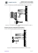
Humidity Control by Humidistat (External Mode)
Humidity controlled externally, using HRO20 humidistat:
T
B
4
T
B
3
T
B
2
T
B
5
T
B
6
Airflow switch
High limit humidistat
Interlock
Control Demand
Room Humidity
Common
24 Vac
24 Vac
T
B
1
1
2
1
2
1
2
3
4
5
1
2
3
4
5
6
1
2
3
1
2
3
T
B
7
HRO20
humidistat
1
2
1
2
1
3
1
4
1
5
1
6
COM
24 VAC
MOD
%RH
1
2
Illustration 41 - Control Signal from HRO20 Humidistat
Summary of Contents for SKG4-E Series
Page 70: ...Notes ...
Page 71: ......

