background image


SKGE3 Gas Fired Humidifier 

Installation Instructions and User Manual


36 

Start-Up 

Start-up 

1.  Proceed to start-up the humidifier, as follow: 


a)  Open  the  front  access  door  of  the  humidifier  cabinet;  make  sure  that  the 

manual drain valve is closed. 


b)  Start up the humidifier by pushing the 

 (ON/OFF) button located on the 

humidifier control panel. 


c)  After 5 seconds, water will start to fill. 

Verify that the water level slowly rises in the water level sight glass located 
on the side of the evaporation chamber 


d)  Verify that there is a humidity demand. 

Humidity demand is displayed on the humidifier LCD screen. 


e)  The humidifier LCD screen will display  the  water level in percentage (%). 

When the display indicates that the water level is at 100%, verify that the 
water level in the water level sight glass is approximately 20mm below the 
safety belt band of the evaporation chamber. 


f)  If there is a humidity demand, the burner combustion blower(s) will start, 

and after approximately 90 seconds the combustion will start. 
From a cold water start, the humidifier will require 5 to 10 minutes to 
produce steam. 
The Humidifier LCD display will indicate water temperature and flue gases 
temperature. 


g)  During normal operation while steam is produced, the water temperature 

must be 100

˚C and the flue gases temperature around 120 to 200˚C. 

Water level percentage must not indicate less than 95%. 


h)  Observe for water, steam and flue gases leaks. 


Combustion Field 

Adjustment 

2.  Please refer to the 

Combustion field adjustment instructions

 enclosed in this 

package to perform this operation 


Safety Test 

3.  Check the location of the air flow switch in the system and its operation by 

stopping the fan. 
With no air movement in the air duct, the humidifier must automatically stop 
the combustion burner(s). 


Drain and Reset 

4.  Turn the humidifier OFF, by pushing the 

 (ON/OFF) push button on the 

control panel. 


5.  Execute a manual drain, by pushing the 

 (DRAIN) push button on the 

control panel. 
A water jet directed on the water level sensor located in the water level sight 
glass will start and create bubbles around it. 


6.  Reset the air flow switch and humidistat(s) to the proper value, if needed. 


End 

7.  The humidifier is now ready for normal operation. 


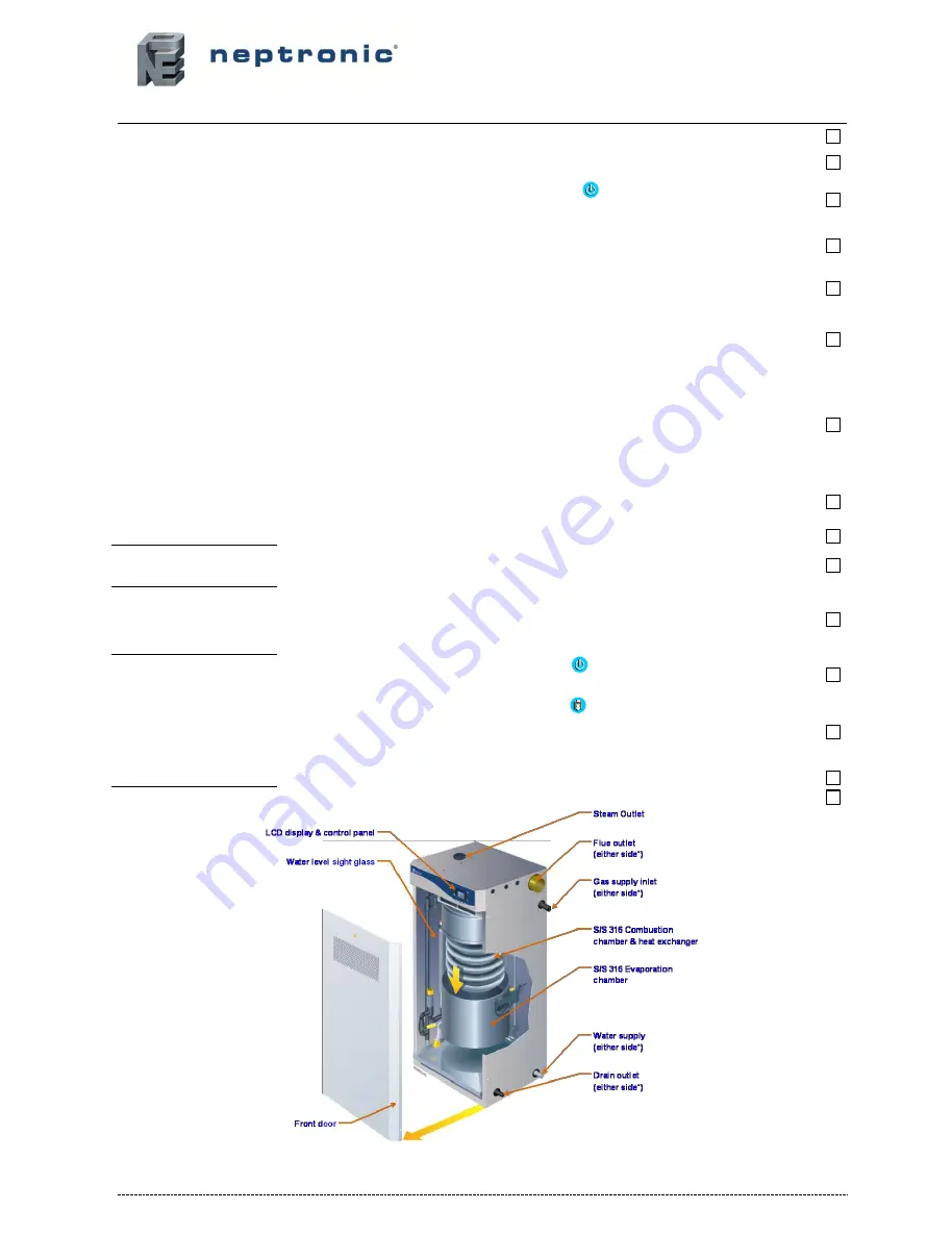
General overview reminder 

– Fig. 50 

All manuals and user guides at all-guides.com

Summary of Contents for SKGE3 Series

Page 1: ...9 Conform to CE requirements PIN 359BQ511 AT BE CH CY CZ DE IE IT GR GB DK MT NL FR IS LT LU NO PT SE ES EE FI HU SK SI TR PL HR RO AL BG LV MK Read and save these instructions SKGE IOM 170803 All man...

Page 2: ...system in accordance to Health Safety regulations and enclosed instructions Carry out a risk assessment of the water system supplying the humidifier by a competent person to ensure the water supply is...

Page 3: ...operation as per the manufacturer s recommendations The application of these instructions is one of the conditions for the application of the warranty The application of these instructions does not e...

Page 4: ...n 28 Stage 8 Electrical Supply and Installation 30 Stage 9 Electrical Control Connections 31 Stage 9 BACnet Interface Set up 34 Initial Verification 35 Commissioning Operation Description 37 Operation...

Page 5: ...N 61000 4 2 Immunity to electrostatic discharges EN 61000 4 3 Immunity to radiated electromagnetic fields EN 61000 4 4 Immunity to electrical fast transients EN 61000 4 5 Immunity to surges EN 61000 4...

Page 6: ...4 5 100 SKGE3 1702 N P 2 170 134 12 6 147 5 7 4 5 100 SKGE3 2002 N P 2 200 144 13 6 158 6 1 4 5 100 SKGE3 2503 N P 3 250 203 19 1 222 8 6 6 0 100 SKGE3 2703 N P 3 270 206 19 4 225 8 7 6 0 100 SKGE3 3...

Page 7: ...l of water SKGE3 0501 N P SKGE3 0701 N P SKGE3 0801 N P SKGE3 1001 N P 1 1 76 1372 610 56 230 460 145 200 SKGE3 1202 N P SKGE3 1502 N P SKGE3 1702 N P SKGE3 2002 N P 2 2 76 1372 1220 560 230 460 610 9...

Page 8: ...N P SKGE3 1702 N P SKGE3 2002 N P 2 38 15 BSPT 1 BSPT 100 SKGE3 2503 N P SKGE3 2703 N P SKGE3 3003 N P 3 38 15 BSPT 1 BSPT 125 SKGE3 3504 N P SKGE3 3704 N P SKGE3 4004 N P 4 38 15 BSPT 1 BSPT 125 Not...

Page 9: ...nlet Dimensions in mm Air inlet Diam J K L M N O SKGE3 0501 N P SKGE3 0701 N P SKGE3 0801 N P SKGE3 1001 N P 1 1 51 448 352 SKGE3 1202 N P SKGE3 1502 N P SKGE3 1702 N P SKGE3 2002 N P 2 2 51 448 352 6...

Page 10: ...V W Empty Full of water SKGE3 0501 N P SKGE3 0701 N P SKGE3 0801 N P SKGE3 1001 N P 1 1867 647 841 611 285 340 SKGE3 1202 N P SKGE3 1502 N P SKGE3 1702 N P SKGE3 2002 N P 2 1867 1308 841 611 472 582 S...

Page 11: ...GE3 Steam Humidifier package may be carried using a fork lift from the underside Caution must be exercised to ensure balanced load before lifting Lifting of SKGE3 Steam Humidifier MUST always be carri...

Page 12: ...e SKGE3 Steam Humidifier and its associated components no special tooling is required above that of a fitter s toolkit Installation Method Statement Stage1 Unit Positioning and Mounting Stage 2 Steam...

Page 13: ...e gases must be vented to the outdoors Locate the humidifier as near as possible to an outside wall or roof so that the flue pipe from the humidifier is short and direct Locate the SKGE3 Steam Humidif...

Page 14: ...umidifier is designed to be installed directly on the floor Provide a level solid foundation for the humidifier Ensure that the floor beneath the humidifier is water proof to withstand any water spill...

Page 15: ...n the flexible hose When using rigid copper pipe insulation must be used to diminish condensation build up Min 7 Correct Installation Single module humidifier with Multisteam Static pressure 50mm Stea...

Page 16: ...ither one of the sides of the humidifier By default the steam outlet will be on the right side of the humidifier when facing the control panel Steam outlet side can be switch to left upon request to f...

Page 17: ...uct size is below a width of 900mm it will be necessary to either fit multiple pipes or use a Multi Steam system Horizontal Duct Horizontal duct 2 manifolds Fig 18 Horizontal duct 3 manifolds Fig 19 V...

Page 18: ...mm feed pipe must be connected to two 2 S A M E2 Steam manifolds with a suitable reduction at the lowest point to allow a 15mm condensate drain from the main steam supply Single Module Humidifiers SKG...

Page 19: ...For installation of Multi Steam units please refer to Neptronic Multi Steam Installation Instructions Horizontal Duct Multi Steam in horizontal duct Fig 24 Vertical Duct Multi Steam in vertical duct...

Page 20: ...1202 SKGE3 1502 SKGE3 1702 SKGE3 2002 Steam pipe work SKGE3 1202 to 2002 Fig 27 Two 76mm steam outlets to a single 108mm feed pipe must be connected to a single Multi Steam with a suitable reduction...

Page 21: ...eam pipe work SKGE3 3504 to 4004 Fig 29 Two 76mm steam outlets to a single 108mm feed pipe must be connected to a single Multi Steam with a suitable reduction at the lowest point to allow a 15mm conde...

Page 22: ...checked for leaks Do not use soap solution or open flame on the humidifier gas train A gas leak detector must be used All leaks MUST be sealed prior to commissioning the humidifier Gas Pipe Diameter...

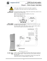
Page 23: ...202 1502 1702 2002 2503 2703 3003 3504 3704 4004 1 2 BSPT Male Water Supply Line Installation To facilitate servicing a shut off valve not supplied must be installed in the water line within 1 meter o...

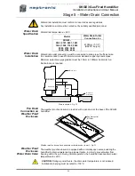
Page 24: ...e 1 5mm in 1000mm horizontal run No drain trap is required Drain connection Fig 32 Pan Drain Connection on Weather Proof Enclosure The weather proof enclosure is provided with a pan drain at the base...

Page 25: ...fficient height above ground level to prevent blocking by accumulated debris The SKGE3 Steam Humidifier has filtered air openings through the front door Do not block or obstruct the air openings of th...

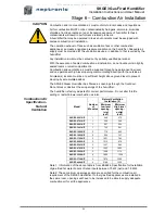
Page 26: ...r elbows Combustion air duct length and flue gases venting pipe must not exceed 30m 1 5m x total number of 90 elbow Combustion air duct must be insulated to avoid condensing around the duct when outsi...

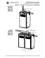
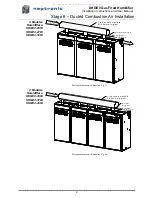
Page 27: ...1001 Ducted combustion air 1 module Fig 35 2 Modules Humidifiers SKGE3 1202 SKGE3 1502 SKGE3 1702 SKGE3 2002 Ducted combustion air 2 modules Fig 36 Combustion air 51m m m inim um Hum idifier inlet 51m...

Page 28: ...3 modules Fig 37 4 Modules Humidifiers SKGE3 3504 SKGE3 3704 SKGE3 4004 Ducted combustion air 4 modules Fig 38 Com bustion air from outside Flue gases Hum idifier inlet 51m m 51m m m inim um 1 to 3 o...

Page 29: ...air tight Failure to do this will result in damage due to moist flue gases condensing Flue Gas Venting Specification The Neptronic SKGE3 Steam Humidifier is a fan assisted condensing positive pressur...

Page 30: ...al 1250 Above below beside or facing any electric or gas meter regulator or relief device When Flue gas terminal is located in car port in residential building Minimum spacing mm Building or other ele...

Page 31: ...l work concerned with electrical installation MUST only be performed by skilled and qualified technical personnel e g electrician or technicians with appropriate training Please observe local codes an...

Page 32: ...played A third interlock switch can be wired between terminals TB1 2 5 If this contact is open operation of humidifier will stop and an Alarm message will be displayed TB1 Interlock and control signal...

Page 33: ...6 7 8 9 1 2 3 4 5 6 1 2 3 R R LAST ANLG OUT 1 2 3 4 5 X 6 7 8 9 DUCT HUMID ROOM HUMID CTRL DEMAND INTER LOCK PD SW ITCH HI LIM 24 VAC 700MA MAX TB1 TB2 JP2 JP1 DS1 O N P1 RS 232 A B TB3 RS 485 COM NO...

Page 34: ...with a switching current of no more than 3 A Operation Alarm contact wiring Fig 46 Common 24 VAC RH Control Signal H R O 2 0 Common 24 VAC RH S H C 8 0 1 3 2 4 5 6 7 8 9 1 2 3 4 5 6 1 2 3 R R LAST ANL...

Page 35: ...election Baud rate Switch 2 Switch 3 9600 OFF OFF 19200 ON OFF 38400 OFF ON 76800 factory setting ON ON See also the BACnet communication module user guide supplied 1 3 2 4 5 6 7 8 9 1 2 3 4 5 6 ANLG...

Page 36: ...fier 9 Confirm that gas is supplied to the humidifier and that the shut off valve located outside the humidifier is closed Once the shut off valve is turned ON check for leaks gas smell or hissing sou...

Page 37: ...r will require 5 to 10 minutes to produce steam The Humidifier LCD display will indicate water temperature and flue gases temperature g During normal operation while steam is produced the water temper...

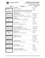
Page 38: ...et up 4 Alarms 5 Diagnostics 6 Com Set up Use the or buttons to scroll up or down and access a menu by pressing the button Within a menu press on the or buttons to pass from one screen to another The...

Page 39: ...maining water in order to prevent growth of bacteria Upon new humidity demand evaporation chamber s will fill up with fresh water and produce steam INPUT SUPPLY TOO LOW Voltage supply is below the min...

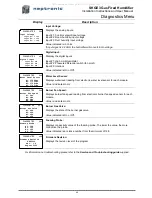
Page 40: ...ated in 100 indicate that the evaporation chamber is full of water During normal operation the value can fluctuate between 95 and 105 Water Temperature Displays the water temperature inside the evapor...

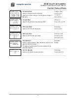
Page 41: ...V Or 4 to 20 mA Room RH Source Selection of room relative humidity source External Com Port Humidity Input Setup Selection of humidity input Voltage or Amp From 0 to 10 V or 2 to 10 V Or 4 to 20 mA H...

Page 42: ...in values KP from 0 to 100 KI from 0 to 100 KD from 0 to 100 Tank Operation Selection of tank operation when SKGE3 humidifier is built with more than one module For optimum humidity control it is reco...

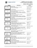
Page 43: ...mber anti freeze temperature If enabled combustion will be ordered to maintain water temperature between 7 and 12 C This screen is not available for humidifiers with the weather proof enclosure option...

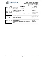
Page 44: ...the language displayed by interactive menus English or Fran ais Default English Time Date Setup Reset of the internal clock Not programmable in this firmware version Default N A Set Alarm Beep ON Sele...

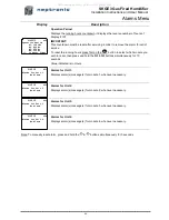
Page 45: ...ed is in Hours Alarms for Unit 1 Displays alarm s message s for module 1 whenever necessary Alarms for Unit 2 Displays alarm s message s for module 2 whenever necessary Alarms for Unit 3 Displays alar...

Page 46: ...lly when the water temperature reaches the proper value Water Temp too high Water holding temperature is above the pre set maximum value humidifier will shut off and cool down until water temperature...

Page 47: ...ule Value is indicated in Hz DIAGNOSTICS 504 Burner Gas Valve H1 OFF H2 OFF H3 OFF H4 OFF Burner Gas Valve Displays the state of the burner gas valve Value indicated is On or Off Foaming Probe Display...

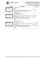
Page 48: ...Configuration mode see the Stage 9 BACnet Interface Set up section of the manual From 0 to 255 Increment 1 Default 0 Device Instance Selection of device instance value This value is locked in order to...

Page 49: ...SKGE3 Gas Fired Humidifier Installation Instructions and User Manual 48 Personal Notes All manuals and user guides at all guides com...

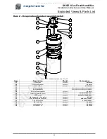
Page 50: ...models SP 3365 9 Combustion blower gas valve assembly See detail 10 Combustion blower gasket All models SP G2104 11 Igniter holder assembly See detail 12 Igniter holder gasket All models SP G2103 13...

Page 51: ...Burner assembly See combustion component detail table 28 Burner assembly gasket All models SP G2111 29 Water temperature sensor All models SW GWATTEMP ASSY 30 AFEC probe All models SW GAFECPROBE ASSY...

Page 52: ...bustion blower and gas valve assembly Fig 54 Combustion component detail table Item Description Part number by Module type Module SKG 100 Module SKG 150 Module SKG 180 Module SKG 200 26 Heat Exchanger...

Page 53: ...l flue pipe SKGE3 2503 to 4004 Flue pipe assembly Fig 56 Item Description Model Part number 47 Flue section SKGE3 2503 to 4004 SP G2201 48 Flue breech pipe gasket All models SP G2107 49 Flue joint fib...

Page 54: ...ded Views Parts List Water level sensor assembly Water level sensor assembly Fig 57 Item Description Model Part number 53 Water level sensor assembly All models SW GWATLEV ASSY 54 Water level sensor A...

Page 55: ...N P 1 x1 SKGE3 0701 N P 1 x1 SKGE3 0801 N P 1 x1 SKGE3 1001 N P 1 x1 SKGE3 1202 N P 2 x1 x1 SKGE3 1502 N P 2 x2 SKGE3 1702 N P 2 x1 x1 SKGE3 2002 N P 2 x2 SKGE3 2503 N P 3 x1 x1 x1 SKGE3 2703 N P 3 x...

Page 56: ...ww neptronic com Toll free in North America 1 800 361 2308 Tel 514 333 1433 Fax 514 333 3163 Customer service fax 514 333 1091 Monday to Friday 8 00am to 5 00pm Eastern time All manuals and user guide...

Reviews: