SKR Humidifier – kit N
User Manual
www.neptronic.com
15
10.2.
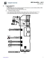
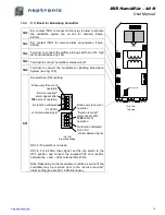
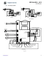
P.C. Board for Modulating Humidifier
TB2
Dry contact (TB2) to connect to fan relay in order to activate
the ventilation system fan on call for humidity (3amp,
24Vac).
TB3
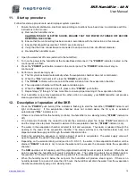
Dry contact (TB3) for remote alarm annunciation (1amp,
24Vac).
TB4
Terminal to connect the airflow proving switch and the high
limit humidistat (see fig.12b)
TB5
Terminal to connect humidifier external cut-off.
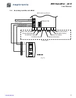
TB6
Terminal to connect the humidistat or Building Automation
System (see fig. 12b)
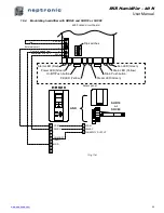
DS1
Dip switches (DS1) setting:
(Fig 15b)
Dip switch setting
DS1-3 : Dip switch is not used
DS1-4: For 4-20mA input signal, set the dip switch to the
OFF position and connect the supplied 500 ohm resistor
between the + and
– of the terminal block TB6.
Note: Depending on the local water conditions, service of the
humidifier may be required prior to the ''service required''
alarm setting (see section 14, Maintenance).
Transformer
TB
2
TB
3
TB
4
JP
3
Dip switches
TB
5
TB
6
O
N
1
2
3
4
JP5 SSR
1
2
1
2
TB
7
TB
8
Relays
(Fig. 15a)
Top view
O
N
1
2
3
4
Drain every
2
hours of
operation
''Service required''
alarm appear after
750
hours of operation
No function attributed
O
N
1
2
3
4
Drain every
6
hours of
operation
''Service required''
alarm appear after
1500
hours of
operation
No function attributed
2-10 VDC
control demand signal
0-10 VDC
control demand signal

