background image

SKR Humidifier – kit N 

User Manual 


www.neptronic.com


20


16.  Types of alarm 

CAUTION:  RISK  OF  ELECTRIC  SHOCK,  POWER  MUST  BE  TURNED  OFF  AT  THE  EXTERNAL 
BREAKER/FUSED DISCONNECT BEFORE REMOVING THE COVER OF THE HUMIDIFIER. 


IMPORTANT:

 A corrective action must be taken before doing a reset. 


The alarm contact (normally open) will close when there is an alarm. 


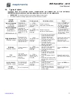
ALARM 

Indicator 

Condition 

Consequences 

Corrective actions 

Reset 

Service required


1.

 Flashing 

continuously 

Operating hours 
exceeded the service 
required alarm hour 
setting (DS1-2) 

Alarm. 

No interruption of 
the operation of the 
humidifier 

Proceed to a service 
(See section 14-Maintenance) 


Press the ''

POWER''

 push 

button to turn OFF the 
humidifier (if necessary). 


Press and hold ''

DRAIN''


and ''

POWER''

 push 

buttons simultaneously for 
ten seconds. These two 
indicators will turn on after 
the ten seconds.  Release 
the push buttons. 

Service required


2.

 Indicator is 

continuously on 


(

SKR

 Humidifier shut off) 

Operating hours 
exceeded by more than 
50 hours the service 
required alarm setting 
(DS1-2)


Alarm. 

The operation of the 
humidifier is 
interrupted


Proceed to a service 
See section 14-Maintenance) 

High temperature 

2 f pause


Temperature in the 
evaporation chamber 
exceeded the preset 
temperature of the high 
temperature switch 

Alarm. 

The operation of the 
humidifier is 
interrupted 

  Check that the static pressure 

inside the duct at the steam 
dispersion tube does not 
exceed 0.5” W.G. (125Pa). 

  Check that the steam hose is 

not blocked or kinked. 

  Check that the water 

connection on the evaporation 
chamber is not blocked. 

Press the reset button on the 
high temperature switch 
device located on the 
evaporation chamber cover. 

Drainage 

3 f pause


Drainage sequence is 
not correct 

Alarm. 

The operation of the 
humidifier is 
interrupted 

  Check that the water 

connection to the evaporation 
chamber is not blocked. 

  Check that the drain piping is 

not blocked. 

Press on the 

DRAIN

 push 

button 

Fill 

4 f pause


Time to fill the 
evaporation chamber 
exceeded the preset 
time in the 
microprocessor 

Alarm. 

The power to the 
heating element is 
interrupted 

  Check that the shut off valve 

installed on the supply water 
line is open. 

  Verify the operation of the fill 

valve. 

  Check that the fill valve strainer 

and the external strainer are not 
blocked. 

Automatic reset

 when the 

proper water level is reached 

Level sensors 

5 f pause 

The level sensors do 
not detect the water 
level correctly 

Alarm. 

The operation of the 
humidifier is 
interrupted 

  Check that the sensors are 

properly connected. 

  Check that the sensors are 

clean. 

Press on the 

POWER

 push 

button 

Power 

Not flashing 

The unit is not powered 

  Check that the main power 

breaker or fused disconnect 
switch is closed 

Automatic reset

 when the 

unit is powered 


Summary of Contents for SKR-14 CASA

Page 1: ...SKR N eng 170426 SKR series Steam Humidifier Kit N Patent Pending Installation instructions user manual READ AND SAVE THESE INSTRUCTIONS...

Page 2: ...installation and operation as per the manufacturer s recommendations The application of these instructions is one of the conditions for the application of the warranty The application of these instruc...

Page 3: ...r supply 8 6 2 Drain connections 9 7 Power supply connections 10 8 Control diagrams 11 8 1 ON OFF Humidifier standard 11 8 2 Modulating Humidifier 12 9 Control panel display 13 10 Description of the c...

Page 4: ...ustable collars to attach the steam hose to the steam outlet 1 female fitting and a braided hose to connect the water supply For modulating humidifier only 1 resistor 500 Ohms 1 2 Humidifier overview...

Page 5: ...Requirements Steam outlet diameter in mm Weight lb kg Voltage V Current A Power KW Empty With water SKR 14 CASA 4 5 2 05 120 12 1 4 7 8 22 22 10 35 16 SKR 25 VILLA 7 5 3 41 240 11 2 5 7 8 22 22 10 35...

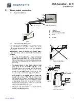
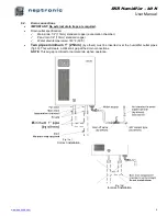
Page 6: ...and 8 0 20m above the humidifier The SKR humidifier should be mounted 39 to 47po 1 to 1 2m above floor for the installation of water supply drain piping and electrical connections Fig 4 4 3 Wall moun...

Page 7: ...ifier fig 7b If the humidifier cannot be the lowest point of the piping install a steam trap s S Type at the lowest point s of the steam supply piping fig 7c This trap should have a minimum height of...

Page 8: ...nimum of 18 460mm of straight duct without obstructions or elbows downstream of the dispersion tube Select an accessible location in the supply air duct For the SKR 14 25 use a template and drill a 1...

Page 9: ...0 C 3 8 10mm standard copper supply water connection To facilitate servicing a shut off valve not supplied should be installed in the water supply line close to the humidifier It is recommended to ins...

Page 10: ...d copper evaporation chamber Pan drain 1 2 13mm standard copper Water drain temperature 140 F 60 C Two pipes minimum 1 25mm by others must be inserted over the humidifier outlet pipes fig 10 This will...

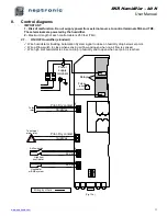
Page 11: ...e required by the humidifier is the same as the available power supply Ensure that the size of the wire conductors is appropriate for the current required by the humidifier A dedicated external breake...

Page 12: ...or Building Automation System signal to close on humidity drop below set point Wire airflow switch to close when sensing air flow and open when no air flow is sensed Wire high limit humidistat to clo...

Page 13: ...t to close on drop in humidity and to open when set point is reached Wire external cut out if required to remotely switch off humidifier TB2 TB3 TB4 To fan relay To external alarm relay Pilot Dry cont...

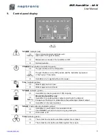
Page 14: ...electric power FILL Indicator yellow O Water supply valve is open O Water supply valve is closed STEAM Indicator green O Humidifier is producing steam at 100 capacity O flashing Modulating humidifier...

Page 15: ...ect the airflow proving switch and the high limit humidistat see fig 12a TB5 Terminal to connect the humidistat or Building Automation System see fig 12a DS1 Dip switches DS1 setting Fig 14b Dip switc...

Page 16: ...DS1 3 Dip switch is not used DS1 4 For 4 20mA input signal set the dip switch to the OFF position and connect the supplied 500 ohm resistor between the and of the terminal block TB6 Note Depending on...

Page 17: ...from control s 12 Description of operation of the SKR Press the POWER push button if the indicator is flashing to start the humidifier POWER indicator will light continuously If the evaporation chamb...

Page 18: ...g down and draining of the evaporation chamber a Press DRAIN push button on the control panel The humidifier will initiate a drain cycle The DRAIN indicator will turn on b The DRAIN indicator is on an...

Page 19: ...warranty 10 Checking the gasket a Check the gasket The gasket should not be cracked The gasket must be replaced a minimum at every second maintenance of the evaporation chamber or after one year of op...

Page 20: ...temperature switch SKR 14 25 30 40 SP 3035 G Water level sensor assembly SKR 14 25 30 40 SW SKRLEV ASSY H Water level sensor tube SKR 14 25 30 40 SP 1025 I Water fill valve SKR 14 25 30 40 SP 6004 J...

Page 21: ...The operation of the humidifier is interrupted Check that the static pressure inside the duct at the steam dispersion tube does not exceed 0 5 W G 125Pa Check that the steam hose is not blocked or ki...

Page 22: ...uation The duct downstream of the dispersion tube is wet The installation of the steam dispersion tube is incorrect The capacity of the humidifier is too high The high limit humidistat is not installe...

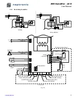
Page 23: ...Connect Powered 208 or 240 Vac Mechanical compartment Transformer On Off Push button Drain Push button Drain LED Yellow Fan LED Green Access panel Alarm LED Red Power LED Green Fill LED Yellow Steam...

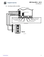
Page 24: ...owered 208 or 240 Vac Relays 208 or 240Vac Transformer On Off Push button Drain Push button Drain LED Yellow Fan LED Green Access panel Alarm LED Red Power LED Green Fill LED Yellow Steam LED Green TB...

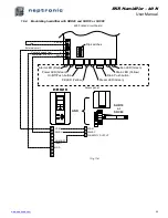
Page 25: ...utton Drain Push button Drain LED Yellow Fan LED Green Access panel Alarm LED Red Power LED Green Fill LED Yellow Steam LED Green SKR Printed circuit board Dip switches TB5 External cut off 24 Vdc TB6...

Page 26: ...Drain LED Yellow Fan LED Green Access panel Alarm LED Red Power LED Green Fill LED Yellow Steam LED Green SKR Printed circuit board Dip switches TB5 External cut off 24 Vdc TB6 ON 1 2 3 4 Control dema...

Page 27: ...SKR Humidifier kit N User Manual www neptronic com 26 Notes...

Page 28: ...u blvd Montreal Qc H4N 1R6 Canada www neptronic com Toll free in North America 1 800 361 2308 Tel 514 333 1433 Fax 514 333 3163 Customer service fax 514 333 1091 Monday to Friday 8 00am to 5 00pm East...

Reviews: