SKR Humidifier – kit N
User Manual
www.neptronic.com
23
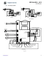
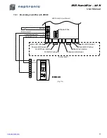
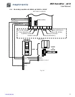
18.2.
Modulating Humidifier
F
3
1
2
3
4
T
B
7
Fuse
Power
supply
terminals
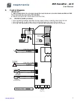
Main Printed
circuit board
Live
Return
Powered 120 Vac
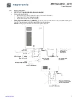
Mechanical compartment
Heating
element
Quick
Connect
JP5 SSR
J1
J6
IN
O
U
T
SKR TRIAC
PCB
(Option)
120Vac
Power
supply
terminals
Main Printed
circuit board
Live
Return
Mechanical compartment
Heating
element
Quick
Connect
JP5 SSR
J1
J6
IN
O
U
T
SKR TRIAC
PCB
(Option)
1
2
1
2
T
B
7
T
B
8
Powered
208 or 240 Vac
Relays
208 or 240Vac
Transformer
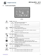
On/Off Push button
Drain Push button
Drain LED (Yellow)
Fan LED (Green)
Access panel
Alarm LED (Red)
Power LED (Green)
Fill LED (Yellow)
Steam LED (Green)
TB
2
TB
3
TB
4
JP
3
Output
connector
Fill valve
High temperature
switch
Water
level
sensor
To fan
relay
To external
alarm relay
Powered - 30mA/
24Vac
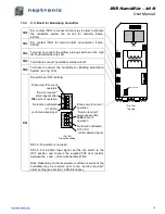
Dip switches
High probe Orange
Low probe White
Mechanical compartment
Pilot - Dry contact
1A/24Vac
Pilot - Dry contact
3A/24Vac
Quick
connect
Common
!
TB
5
Airflow switch
High limit
humidistat
External
cut-off
24 Vdc
24 Vdc
O
N
1
2
3
4
+
-
Control signal
from humidistat
or BMS system
0-10Vdc
2-10Vdc
4-20mA
TB
6
24 Vac
(Fig. 17b)

