SKR Humidifier – kit N
User Manual
www.neptronic.com
5
4.
Mechanical installation
4.1.
General recommendations
CAUTION: RISK OF ELECTRIC SHOCK. DISCONNECT THE HUMIDIFIER FROM THE ELECTRIC
SUPPLY BEFORE PROCEEDING TO THE MECHANICAL INSTALLATION.
IMPORTANT:
Mechanical installation should conform to Local and National Codes.
Location: Plan a location which is easy to access in order to permit a proper inspection and servicing of
the humidifier.
Do not install humidifier where failure of the appliance could cause damage to the building structure or to
costly equipment.
This location should be well ventilated; the ambient temperature should not exceed 85
F (30
C).
The maximum distance between the humidifier and the steam dispersion tube in the ventilation duct
should not exceed 6 feet (1.8m) (maximum length of the steam hose).
4.2.
Positioning
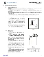
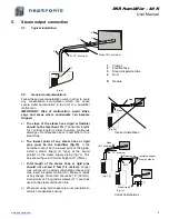
The front panel and the left side (electrical
compartment) should be accessible in order to
permit
easy
servicing
of
the
humidifier.
Leave a clearance of 36” (0.91m) from the front
panel, 12” (0,30m) from the left side, 6” (0.15m)
from the right side and 8” (0.20m) above the
humidifier.
The
SKR
humidifier should be mounted 39” to 47po
(1 to 1,2m) above floor for the installation of water
supply, drain piping and electrical connections.
(Fig. 4)
4.3.
Wall mounting
IMPORTANT:
1. Risk of malfunction. The humidifier must
be level.
2. Risk of overheating. Do not block the
ventilation openings located on the top,
front, sides and rear of the cabinet.
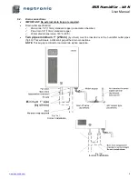
Check the solidity of the chosen support or wall
(bricks, concrete, stud partition wall, etc) on which
the humidifier will be mounted (see page 4 for the
weight of the unit).
Use the keyholes located on the back panel of the
humidifier.
Drill holes for the upper anchors (holes with
eyelets) into the support or wall as per dimensions
specified in the table (fig.5). The hole dimensions
(diameter and depth) should be in accordance
with the recommendations of the chosen anchors.
If necessary, install bolt anchors.
Insert the 2 screws (holes with eyelet) of a
minimum diameter of 1/4” (6mm) (screws are not
supplied).
Leave a clearance between screw heads and wall
in order to permit the mounting of the humidifier.
Hang the humidifier on the 2 screws.
When the humidifier is positioned on the screws,
tighten the screws to secure the humidifier.
(Fig. 5)
Front view
Model
Dimensions (mm)
A
B
C
SKR
2”
(51)
3.06”
(78)
1.44”
(37)


