Evaporative Cooling Humidifier
Installation Instructions and User Manual
www.neptronic.com
Page | 7
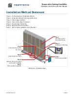
Stage 1 – On Site Assembly of Evaporation Module
On site assembly of the SKV evaporation module is necessary when its height and width are incompatible with
maximum shipping dimensions.
CAUTION
. Risk of injury. Some sheet metal parts might present sharp edges and some handling and
assembly will require working with a ladder. We recommend wearing protective gloves and any
appropriate other protective equipment during handling and assembly of the SKV evaporation module.
We recommended installing the SKV evaporation module into a waterproof AHU or duct section. The SKV
evaporation module is a self-contained humidifier/cooler however; leaks might occur at the water and drain
connection point.
WARNING: Risk of malfunction. SKV evaporation module must be level in the 2 plan
directions.
Bottom tank, main support beam and pump skid will usually be pre-assembled at the factory before delivery.
However, the main support beam for the evaporative media panels as well as the pump skid can be easily
removed and re-installed as indicated in steps 1 and 9. Tools required:
Philips screw driver size #2 & #3
Wrench sizes 7/16’’ (11mm) and 5/16’’ (8mm)
Level
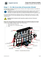
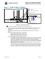
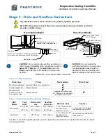
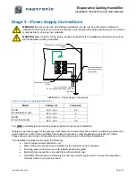
Illustration 5 - Evaporation Module Assembly
!
!
1A
1B
1C
2A
2B
2C
3A
3B
3C
4A
4B
4C
5A
5B
5C
6A
6B
6C
Step 1
Main support beam
(factory assembled)
Step 2
Side frame sections
(factory assembled if H=W)
Step 3
Side frames (x2)
Step 4
Top frame
Step 5
Media panels
Step 7
Holding rail (1 per level)
Step 8
Water distribution drawers
Step 9
Pump skid assembly
(factory assembled)
Step 10
Drain manifold assembly
(factory assembled)
Step 6
Panel link bracket
(at least 1 per level)
Step 11
Water distribution hoses
(1 per drawer)


