Evaporative Cooling Humidifier
Installation Instructions and User Manual
www.neptronic.com
Page | 8
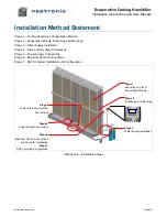
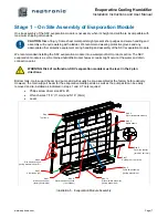
Step 1 (optional): Main Support Beam
The evaporation media panel’s main support beam is assembled at the factory. However its position can be
adjusted depending on the evaporative media panels’ depth. To do so, remove the screws’ protective caps and
remove the Philips screws. Adjust, re-install the screws and re-insert the protective caps.
Step 2 (optional): Side Frame Sections
If the height of the evaporation module is greater than its width, assemble the side frame section along with the
holding rail support. Install the four lock washers and nuts and then tighten using a 7/16’’ (11mm) wrench.
Step 3: Side Frames
Assemble the two side frames onto the bottom tank. Install the six lock washers and nuts on each side and then
tighten using a 7/16’’ (11mm) wrench.
Step 4: Top Frame
Install the top frame onto the two side frames.
CAUTION
. This part can be very long and might require the help of 2 people to be safely installed.
Install the three lock washers and nuts on each side. Do not tighten the nuts, as a final adjustment of the
assembly will be required after all the media panels and water distribution drawers are installed at steps 5 and 8.
Step 5: Media Panels
Install the media panels onto the evaporation module frame. We recommended installing them row by row, and
not column by column. Make sure that each media panel is properly installed into the one below.
Step 6: Media Panel Link Bracket
Install at least one media panel link bracket per level. This bracket is designed to re-enforce the structure by
holding together the media panel and holding rail. Loosen the top two Philips screws from adjacent media panel
frames, insert the bracket, and then tighten the two Philips screws.
Step 7: Holding Rail
Install one holding rail per level. Insert the holding rail onto at least one link bracket and engage the latches into
the holding rail supports on both sides.
Note: In case the SKV evaporation module is equipped with a droplet separator (air velocity above
600FPM), repeat steps 5 to 7 for the installation of droplet separator panels.
Step 8: Water Distribution Drawers
Install the water distribution drawers onto the top frame (step 4) and adjust the top frame position to ensure proper
sliding of the drawers. Confirm proper positioning of the top frame (step 4) and tighten the three nuts on each side.
Step 9 (optional): Pump Skid
The pump skid assembly is installed at the factory before shipping. If you need to remove it, first disconnect the
electrical quick connector of the drain and then remove the Philips screw.
Step 10 (optional): Drain Manifold
The drain manifold assembly is installed at the factory before shipping. If you need to remove it, disconnect the
drain hose from the bottom tank, and open the clamp maintaining the drain manifold assembly by removing the
5/16’’ (8mm) nut. The drain manifold assembly can be directed either on the right-hand side (by default) or on the
left-hand side of the bottom tank.
Step 11: Water Distribution Hoses
Install the water distribution hoses between the top drawers and the circulation pump manifold or solenoid valve
outlets, by pushing each hose into the push-in connectors.
!


