Evaporative Cooling Humidifier
Installation Instructions and User Manual
www.neptronic.com
Page | 9
Stage 2 – Evaporation Module Positioning and Mounting
General Considerations
Consider the following points before deciding the location for the Evaporative Cooling Humidifier steam
distribution system:
Plan a location that is easy to access and permits an easy inspection and servicing of the Evaporative
Cooling Humidifier.
Do not install the Evaporative Cooling Humidifier where failure of the appliance could cause damage
to the building structure or to other expensive equipment.
Verify that the construction of the duct or AHU wall is suitable to support the maximum weight when
the evaporation module is wet.
We recommend installing the SKV evaporation module into a waterproof AHU or duct section. The
SKV evaporation module is a self-contained humidifier/cooler however; leaks might occur at the water
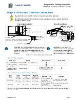
and drain connection point. Install a drain outlet connection at its lowest point within the cooling or
humidification section.
Construct the drain pipe in such a way that there is no water accumulation and stagnation.
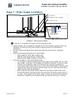
Make provision either on one side or both sides of the AHU or duct for water supply, drain line(s), and
electrical conduit to the evaporation module.
The SKV Evaporative Cooling Humidifier accepts the water supply, drain, overflow piping, and
electrical connections from the right-hand or left-hand side of the evaporation module.
Positioning the Evaporation Module
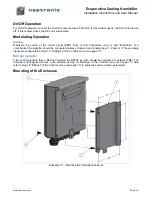
Level the evaporation module properly in order to ensure proper distribution of water (see Illustration
6 - Positioning and Mounting). Make sure that the drain outlet is at the lowest point of the unit.
Do not leave any empty space around the evaporation module. In case there is some empty space,
install blanking plates to prevent air passage.
The unit is custom made to fit the AHU or duct dimension however; to allow easy installation and service a
space of 2in (51mm) on both sides and 2in (51mm) on top of the evaporation must be planned.
Provide a minimum access of 24" (600mm) downstream of the evaporation module for installation,
inspection, commissioning, and maintenance. Also provide the same clearance, 24" (600mm)
upstream, for easy commissioning and maintenance.
Provide access to the sides of the unit through doors.
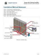
Illustration 6 - Positioning and Mounting
Mounting the Evaporation Module
Secure the evaporation module to the AHU or duct by screws and bolts (not supplied) of suitable size.
Attach the evaporation module in such a way that it will not vibrate or move under air velocity and
pressure.
Level in this direction
Level in this direction
Attachment point
(x4)


