Evaporative Cooling Humidifier
Installation Instructions and User Manual
www.neptronic.com
Page | 13
Stage 6 – Electrical Control Connections
WARNING
. All work concerned with electrical installation should only be performed by skilled and
qualified technical personnel, such as electricians or technicians with appropriate training. The customer
is responsible for ensuring their suitability.
WARNING
. Risk of electric shock. Isolate all power supplies before installation and maintenance of the
SKV Evaporative Cooling Humidifier.
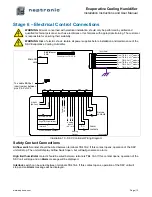
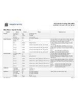
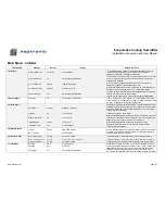
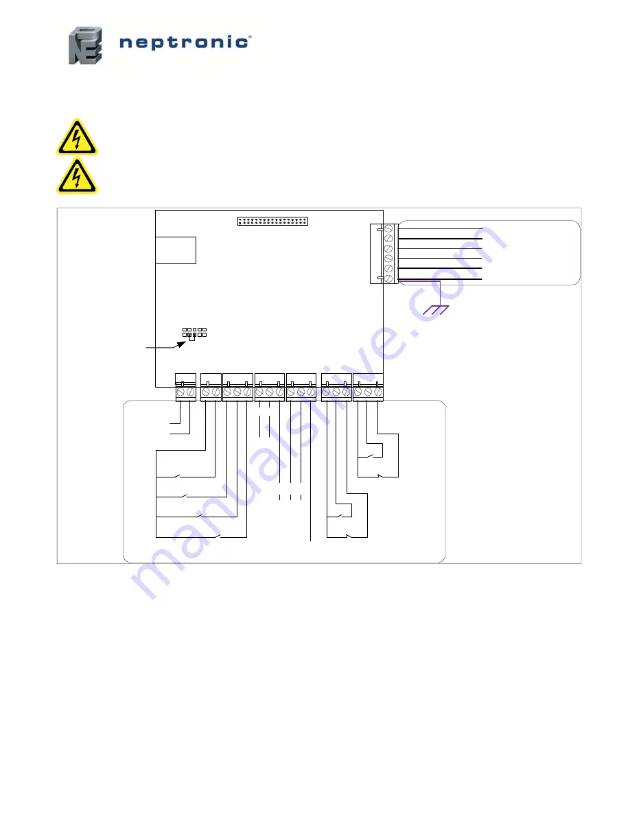
Illustration 10 - SKV Controller Wiring Diagram
Safety Contact Connections
Airflow switch
contact should be wired between terminals TB4 1&2. If this contact opens, operation of the SKV
unit will stop. The unit will display Airflow Switch open, but will
not
generate an alarm.
High limit humidistat
contact should be wired between terminals TB4 1&3. If this contact opens, operation of the
SKV unit will stop and an
Alarm
message will be displayed.
Interlock
switch can be wired between terminals TB4 1&4. If this contact opens, operation of the SKV unit will
stop and an
Alarm
message will be displayed.
SKV Master
PCB
TB3
TB4
TB5
TB2
TB1
TB
6
SD1
LCD1
Air Flow Switch
High limit Humidistat
Interlock
On/Off demand contact
NO
NC
NO
NC
Alarm
contacts
Service
contacts
Co
mm
on
24
V
ac
(by others)
A+
B-
RS-485
(BACnet)
(by others)
24
Va
c
purple
Micro SD
card
From TB 12-1 of 1
st
module
From TB 12-2 of 1
st
module
To TB 12-3 of 1
st
module
From TB 12-4 of 1
st
module
To TB 12-5 of 1
st
module
To TB 12-6 of 1
st
module
Analog
Inputs
(AI1 - AI3)
3
- +
2
1
Analog
Output
To enable BACnet,
insert jumper between
pins 3 & 5 of JP2
Connector to LCD PCB


