Evaporative Cooling Humidifier
Installation Instructions and User Manual
www.neptronic.com
Page | 21
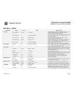
Main Menu - Installer
INSTALLER
Settings
Default
Range Notes/Conditions
4A) Service
Cleaning Interval:
3 months
3 to 12 months
A “Service Warning” appears 100 hours before the due date. A
“Service Alarm” appears on the due date. The due date is
displayed in
Step 3B
of the Diagnostics menu.
Silver Ion Notice:
Off
On (Enable), Off (Disable)
The due date is variable based on water flow and time in use. If set
to
On
, a “Service Alarm” appears on the due date. If set to
Off
,
notification is disabled.
UV Lamp Notice:
2000 h
1500 to 3000 hours
A “Service Alarm” appears on the due date. The due date is
displayed in
Step 3C
of the Diagnostics menu.
On Service Alarm:
Unit OFF
Unit ON, Unit OFF
Determines whether the unit remains turned on or off through the
duration of any service alarm (e.g. UV lamp service alarm)
Water Lvl Calib.:
Off
On (Enable), Off (Disable)
Performs an automatic calibration of the capacitive water level sensor.
If set to
On
, every time the tank is filled.
If set to
Off,
on start up and if the sensor becomes uncalibrated.
4B) Occupancy
Schedule: Off
On
(Enable), Off (Disable)
If
Int. in Temp
or
Int. in RH
at step 1A “Control Mode” in Controls
menu. Select
On
to enable the occupancy schedule defined at step
2C “Occ. Schedule” in the System Setup menu.
4C) Auto Drain
Auto Drain:
Interval
Schedule or Interval
Appears only with Recirculation models. The drain schedule is not
available for Direct Feed models. If set to
Schedule
, refer to “Drain
Schedule” in step 2B of the System Setup menu. If set to Interval,
refer to Interval time below.
Interval:
4h
1 to 24 hours
If
Interval
at step 4C “Auto Drain”.
Module Inactivity:
6 h
4 to 72 hours
Maximum allowable time of inactivity for the evaporation module. If
there was no demand for the entire period, the unit will perform an
automatic drain sequence (empty and fill the tank).
Inlet Inactivity:
7 days
1 to 7 days
Maximum allowable time of inactivity for the water inlet.
Inlet Drain Time:
10s
1 to 60 seconds
Regulates water line drain time in the case where the Inlet
Inactivity delay is attained.
4D) Water Dilution
Interval:
30 min
30 to 1500 minutes
Set the interval between each water dilution cycle and the number
of cycles. These values are determined by the inlet water quality
as defined in Dilution on page 22.
No. of Cycles:
2
0 to 255 cycles
4E) Sensor Offset
Room RH Sensor:
0 %RH
-10.0 to 10.0 %RH
If
External
(Ext.AI1, Ext.AI2, Ext.AI3) at step 1A “Room RH Src”.
Room Temp Sensor:
0 °C/°F
-5.0 to 5.0°C (- 9.0 to 9.0°F)
If
External
(Ext.AI1, Ext.AI2, Ext.AI3) at step 1A “Room Temp Src”.
High Limit Sensor:
0 %RH
-10.0 to 10.0 %RH
If
External
(Ext.AI1, Ext.AI2, Ext.AI3) at step 1A “High Limit Src”.
4F) Test Mode
Duration:
5 min
5 to 60 minutes
When the Test State is set to
On
, you can simulate any demand
value and navigate through any of the menus. The red Alarm LED
illuminates to indicate that you are in test mode and the screen
displays the remaining time that device will be in test mode. To
exit, set the Test State to
Off
or wait for the test duration to elapse.
Demand:
0 %
0 to 100 %
Test State:
Off
On (Enable), Off (Disable)

