Evaporative Cooling Humidifier
Installation Instructions and User Manual
www.neptronic.com
Page | 23
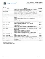
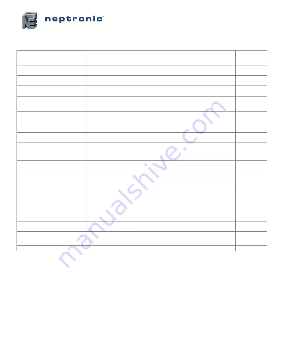
Alarms
Display Description
Alarm
Reset
Air flow open
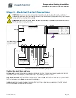
Indicates that the air flow sensor is open. Verify that the signal from the air flow sensor is
present at the SKV controller’s input on the PCB (see schematic).
Automatic
High limit item open
Indicates that the high limit item is open. Verify that the signal from the high limit (duct)
sensor is present at the SKV controller’s input on the PCB (see schematic).
Automatic
Interlock open
Indicates that the interlock and the cut-out circuitry are open. Verify that the signal from
the interlock contact is present at the SKV controller’s input on the PCB (see schematic).
Automatic
Room temp sensor fault
Indicates that the room temperature sensor is defective or incorrectly wired.
Manual *
Room RH sensor fault
Indicates that the room humidity sensor is defective or incorrectly wired.
Manual *
High limit sensor fault
Indicates that the high limit sensor is defective or incorrectly wired.
Manual *
Module # timeout
Indicates that module is not communicating. Verify wiring of the communication line (see
schematic)
Automatic
Output limited warning
Indicates that the output capacity of one or more modules is limited by one of the
following:
- High limit cut-out
- Analog high limit RH
Automatic
Module # service warning
Appears 100 hours before due date of next unit cleaning. This “Cleaning Interval” (3-12
months) is set by the Installer at step 4A in the Installer menu.
Manual †
Module # service alarm
Indicates that the due date for servicing one of the following has arrived:
- Service and clean the evaporative modules
- Replace the silver ion cartridge
- Change the UV lamp
Manual †
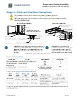
Module # drain fault
Indicates that the low water level float sensor was not reached at the end of the drain
sequence. Verify and remove any obstructions in the drain line.
Manual *
Module # inlet fault
Indicates that the high water level float sensor was not reached within the programmed
delay. Verify and remove any obstructions in the water inlet line and verify that the stop
valve is not closed.
Manual *
Module # water level sensor fault
Indicates that the capacitive water level sensor is defective.
Verify the sensor’s general condition and ensure the proper connection of the wire jacket
between the sensor and the PCB of the evaporation module.
Manual *
Module # water temperature fault
Indicates that the water temperature sensor located within the capacitive water level
sensor is defective. Verify the sensor’s general condition and ensure the proper
connection of the wire jacket between the sensor and the PCB of the evaporation
module.
Manual *
Module # water level alarm
Indicates that the water level is not calibrated properly.
Automatic
Module # high water temperature alarm
Indicates that the water temperature in the tank is above 77
˚
F [25
˚
C], which is a risk for
developing Legionellosis. Verify the temperature of the supply water.
Automatic
Module # high water temperature fault
Indicates that the water temperature in the tank is above 77
˚
F [25
˚
C] even after two
drain or fill cycles, which is a risk for developing Legionellosis. Verify the temperature of
the supply water.
Manual *
Module # water float fault
Water level float is stuck.
Automatic
* (step 3A in Diagnostic menu)
† (step 3B or 3C in Diagnostic menu)


