background image


Evaporative Cooling Humidifier

 Installation Instructions and User Manual


www.neptronic.com


Page | 24 


Servicing and Maintenance 


This humidifier must be installed, operated, and maintained by suitably qualified personnel and in 
accordance with this manual. 

Preventative Maintenance 

The SKV Evaporative Cooling Humidifier requires both inspection and service at regular intervals. The frequency of 
servicing depends on factors such as water quality, capacity and the number of hours in operation. It is recommended to 
inspect and service the evaporation module after 200 hours post commissioning. This inspection is necessary to 
determine the frequency of both inspection and service. 

Verification List 

Perform the following activities regularly to ensure optimal performance and operation of the evaporative module(s).  

  Check for water leaks. 

  Check for stagnant water. 

  Observe the operation of the water flow and evaporation cycle. 

  Check drain operation and flow. 

  Ensure that all electrical connections are secure. 

  Ensure that the 5µ water PP pre-filter is not clogged. 

  Verify if the Silver Ion “service warning” has appeared. If so, replace the Silver Ion dosing cartridge 

  Ensure that the air duct filter upstream of the SKV evaporation module is clean. 

  Check for any accumulation of dirt in the bottom of the tray. If there is a significant presence of impurities, 

clean the tank at the bottom of the unit.  

  Check the flow control at the output of the pump and clean or replace if necessary. 

  Ensure that the water supply hoses at the top of the evaporation module are clean and in good condition. 

  Remove the water distribution trays at the top of the evaporation module and make sure they are clean, clean 

if necessary.  

  Remove the cassette containing the media and remove / clean any residue or deposits accumulated on the 

media or frames. 

Water Sampling and Testing (Hygiene) 


Legionella disease can be fatal. Maintain and control the water system of SKV Evaporative Cooling 
Humidifier according to the local Health & Safety regulation codes. 

SKV Evaporative Cooling Humidifier has been designed to minimise any possible risk of Legionellosis growth. However, 
perform the following checks in order to reduce the growth of Legionellosis: 

  Conduct a risk assessment of the water system by a competent authority. 

  Implement appropriate inspection and control measures. 

  Maintain water temperature below 68°F [20°C]. 

  Maintain a clean, drinking quality water supply. 

 Avoid 

water 

stagnation. 

  Carry out regular microbiological testing of water (counting the number of bacterial units).  

Refer to the ISO 5667-1 standard (Water quality - Sampling - Part 1: Guidelines for the design of programs 
and sampling techniques) 

  Clean and disinfect the system regularly. Refer to Legionella and the prevention of legionellosis, by World 

Health Organization 2007, ISBN 92 4 156297 8 for more detailed advice on control measures. 

  Apply disinfection measures based on the results of visual inspection and microbiological tests.  

Summary of Contents for SKV Series

Page 1: ...SKV Evaporative Cooling Humidifier 140508 docx Evaporative Cooling Humidifier SKV Series Installation Instructions and User Manual Read and save this manual...

Page 2: ...to research and development we provide innovative products and technologies for the ever evolving challenges of the HVAC industry Exporting over 70 of our sales we have an exclusive distribution netw...

Page 3: ...nsible for ensuring the suitability of the technical personnel Please observe local regulations concerning the provision of electrical installations Health Safety Installation maintenance repair work...

Page 4: ...larly refer to service section of the present Installation Instructions and User Manual WARNING Risk of Legionnaires disease which can be fatal SKV Evaporative Cooling Humidifier must be installed ope...

Page 5: ...ning and Mounting 9 General Considerations 9 Positioning the Evaporation Module 9 Stage 3 Water Supply Installation 10 Stage 4 Drain and Overflow Connections 11 Stage 5 Power Supply Connections 12 Sta...

Page 6: ...embly 7 Illustration 6 Positioning and Mounting 9 Illustration 7 Water Supply Installation 10 Illustration 8 Drain and Overflow Connections 11 Illustration 9 Power Supply Connections 12 Illustration 1...

Page 7: ...cooling as a result of the transfer of energy when the water evaporates In order to prevent any possible carry over an optional droplet separator can be added at any time during the life of the SKV Ne...

Page 8: ...W consumption ensuring an environmentally friendly application Four humidification efficiencies 65 75 85 and 95 Inorganic and inflammable material UL900 Class 1 Minimum blanking plates resulting in lo...

Page 9: ...Description Evaporation Module Frame Material Stainless Steel Grade 304 Evaporation Media Material Glass fibre material bonded with a special inorganic compound Evaporation Media Fire Rating European...

Page 10: ...Any personnel handling or lifting the SKV Evaporative Cooling Humidifier must follow the Lifting Operations and Lifting Equipment Regulations 1998 and Approved Code of Practice L113 The regulation im...

Page 11: ...s the customer s responsibility to ensure that the operators are trained in handling heavy goods and to enforce the relevant lifting regulations The Evaporative Cooling Humidifier MUST always be handl...

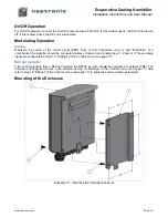
Page 12: ...Overflow Connections Stage 5 Power Supply Connections Stage 6 Electrical Control Connections Stage 7 SKV Controller Installation and Configuration Illustration 4 Installation Stages Stage 5 Power Sup...

Page 13: ...rain connection point WARNING Risk of malfunction SKV evaporation module must be level in the 2 plan directions Bottom tank main support beam and pump skid will usually be pre assembled at the factory...

Page 14: ...ne media panel link bracket per level This bracket is designed to re enforce the structure by holding together the media panel and holding rail Loosen the top two Philips screws from adjacent media pa...

Page 15: ...and electrical conduit to the evaporation module The SKV Evaporative Cooling Humidifier accepts the water supply drain overflow piping and electrical connections from the right hand or left hand side...

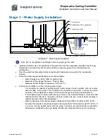
Page 16: ...nge of water qualities such as reverse osmosis RO or tap water If the humidifier is connected to hard water it will result in scale build up on the evaporative module and will require frequent cleanin...

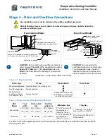
Page 17: ...x Overflow separated Always required x Main drain and overflow combined to a common pipe Always required if evaporation module over 30 762mm or if main drain is not lifted to drain inlet Table 5 Wate...

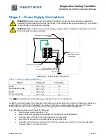
Page 18: ...es for over current protection Isolate the electrical supply for the purpose of emergencies and servicing We recommend installing a disconnect switch within 1m 3 3ft of the humidifier The isolator mus...

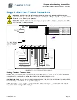
Page 19: ...op The unit will display Airflow Switch open but will not generate an alarm High limit humidistat contact should be wired between terminals TB4 1 3 If this contact opens operation of the SKV unit will...

Page 20: ...thermostat or a combination the signal s should be connected between Common and Analog input 1 2 and or 3 These analog inputs are configurable at step 1A Settings of the Controls menu see page 17 BAC...

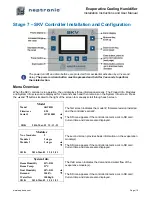
Page 21: ...each screen Model The first screen indicates the model firmware revision installed and the controller s serial The SD icon appears if the controller detects a micro SD card Current time and date are...

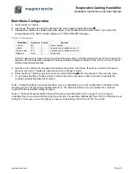
Page 22: ...us such as Controls will be unlocked automatically D Use the and buttons to increase and decrease the values Use the buttons to scroll to the next or previous menu item Values are saved as soon as a c...

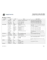
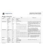
Page 23: ...H at 1A Control Mode Integral Ramp 0 5 C 0 9 F or 5 0 RH 0 5 to 5 0 C 0 9 to 9 0 F or 1 0 to 20 0 RH If Int in Temp or Int in RH at 1A Control Mode Deadband 0 1 C 0 2 F or 2 0 RH 0 5 to 5 0 C 0 9 to 9...

Page 24: ...nt 3 Unused Unused Wait Start Drain Stop Drain 00 00 to 23 59 Event 4 Unused Unused Wait Start Drain Stop Drain 00 00 to 23 59 2C Occ Schedule Occupancy schedule disabled n a n a The drain schedule is...

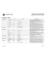
Page 25: ...been cleaned set this value to Yes to reset the Cleaning Due On date and Last Cleaning date Total Runtime 0000 h Displays total number of hours the unit is in function 3C Service Last Silver Ion YY MM...

Page 26: ...rl uC Temp Current value C or F Controller microprocessor temperature Ctrl PCB Temp Current value C or F Controller PCB printed circuit board temperature Module uC Temp Current value C or F Module mic...

Page 27: ...ble for Direct Feed models If set to Schedule refer to Drain Schedule in step 2B of the System Setup menu If set to Interval refer to Interval time below Interval 4h 1 to 24 hours If Interval at step...

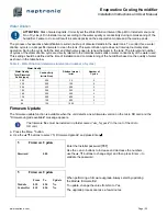
Page 28: ...d commissioning of the humidifier based on the quality of water as shown in the table below Table 8 Water Dilution determine interval and number of cycles Water Quality Dilution Interval min Number of...

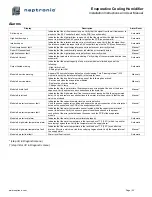
Page 29: ...ate for servicing one of the following has arrived Service and clean the evaporative modules Replace the silver ion cartridge Change the UV lamp Manual Module drain fault Indicates that the low water...

Page 30: ...f the unit Check the flow control at the output of the pump and clean or replace if necessary Ensure that the water supply hoses at the top of the evaporation module are clean and in good condition Re...

Page 31: ...orm the following functions Assess the situation for any security risk with the person responsible for health and safety of the building Check records namely sample results of microbiological testing...

Page 32: ...ical testing of water Once steps 1 4 are completed the air system central air or ventilation system and the Evaporative Cooling Humidifier can be restarted in auto mode A new microbiological test shou...

Page 33: ...the de scaling solution is complete Note The effect of the de scaling solution will vary depending on the condition of the media s material For an improved effect the above process may have to be rep...

Page 34: ...lation of the water distribution drawers Loss of performance The humidifier cassette is blocked or damaged Check for the damaged media cassettes and replace if required Ensure that the humidifier medi...

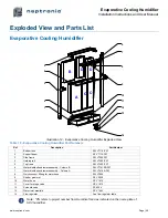
Page 35: ...ame SW V7350PN 4 Holding rail SW V7200 PN 5 Top frame SW V7400 PN 6 Water distribution drawer assembly Column B SW V77410B PN 7 Water distribution drawer assembly Column A SW V7410A PN 8 Quick connect...

Page 36: ...75C PN 85 150mm depth SP VM85C PN SW VM85C PN 95 200mm depth SP VM95C PN SW VM95C PN D Media panel top right 65 75mm depth SP VM65D PN SW VM65D PN 75 100mm depth SP VM75D PN SW VM75D PN 85 150mm depth...

Page 37: ...ponents which on examination by Neptronic are found to be defective Product or component replaced or repaired under warranty will be sent back to the purchaser standard ground freight paid by Neptroni...

Page 38: ...Evaporative Cooling Humidifier Installation Instructions and User Manual Notes...

Page 39: ...Evaporative Cooling Humidifier Installation Instructions and User Manual...

Page 40: ...u blvd Montreal Qc H4N 1R6 Canada www neptronic com Toll free in North America 1 800 361 2308 Tel 514 333 1433 Fax 514 333 3163 Customer service fax 514 333 1091 Monday to Friday 8 00am to 5 00pm East...

Reviews: