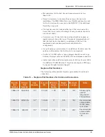
Using the AEA 140-525 Antenna Analyzer
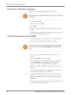
Complete the following steps to configure the analyzer.
This procedure assumes that the analyzer has not been configured
prior to use.
1. Turn the analyzer
ON
.
2. Type the frequency:
46000.
3. Press
Enter
.
4. Set the value next to
WID
on the screen to
20
using the width
buttons.
5. Set the reading to return loss by pressing
F1
three times. (Press it
slowly; the unit should beep each time.)
Taking the Reading and Calculating VSWR
1. Connect the analyzer to the feed line in place of the R450 DC.
2. Configure the analyzer using the preceding procedure.
Be sure that there is not a vertical line running through the display
in the plot area. If there is, press
EXAM PLOT
and it should go
away.
3. Allow the analyzer reading to stabilize, between 10 and 20
seconds.
4. Press
EXAM PLOT
to freeze the display.
5. Move the cursor (the vertical line in the middle of the screen)
using the
FREQ
arrows to approximately the R450 DC's
frequency. (It moves to within 100KHz of a frequency.)
6. Read the value next to
RETL
on the display. This is the return
loss value.
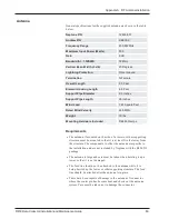
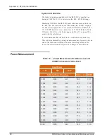
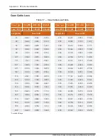
7. Find the loss attributed to the coax (based on the coax type and
feed line length) using Table 17 on page 94.
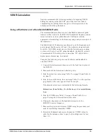
8. Calculate the adjusted return loss using the following formula.
Return Loss (from Table 5) - (2 x Cable Loss) = Corrected
Return Loss.
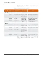
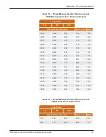
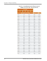
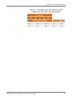
9. Find the VSWR (using the Corrected Return Loss value) Table 15
on page 90 or Table 16 on page 91.
96
R450 Data Collector Installation and Maintenance Guide
Appendix A: RF Antenna Installation
Summary of Contents for R450
Page 2: ......
Page 3: ...R450 Data Collector Installation and Maintenance Guide ...
Page 8: ...This page intentionally left blank ...
Page 143: ......

