Figures
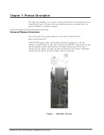
Figure 1 – R450 Data Collector
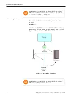
Figure 3 – Wall-Mount Installation
Figure 7 – R450 MHz Antenna P/N 12896-001
Figure 8 – RF 450 MHz Antenna Cable and Trench
Figure 9 – Pole Seated in Ground
Figure 10 – Assembling Strut Channels
Figure 11 – Mounting Hardware Stack Detail
Figure 12 – Positioning the Strut Channel
Figure 13 – Tightening the Bolts of the Strut Clamps
Figure 14 – RF 450 MHz Antenna Connection
Figure 15 – Antenna Connections
Figure 17 – Items for GPRS or Wi-Fi Antenna
Figure 18 – Attaching the GPRS or Wi-Fi Antenna
Figure 19 – Tighten Bolt for GPRS Antenna
Figure 20 – Cable to GPRS Antenna
Figure 21 – GPRS Antenna Connection at Base
Figure 22 – Weatherizing Connections
Figure 23 – Weatherizing the Base Connection
Figure 24 – Weatherizing the Antenna Connection
Figure 25 – AC Wiring Threaded Through Base (120V AC Installation)
Figure 26 – Attaching the Black Wire
Figure 27 – Attaching White Wire
Figure 28 – R450 DC Wiring Diagram (120V AC Illustration)
Figure 29 – USB Port on CPU Board
Figure 30 – Main Disconnect Breaker Switch
R450 Data Collector Installation and Maintenance Guide
xiii
Summary of Contents for R450
Page 2: ......
Page 3: ...R450 Data Collector Installation and Maintenance Guide ...
Page 8: ...This page intentionally left blank ...
Page 143: ......


