background image

Page 7

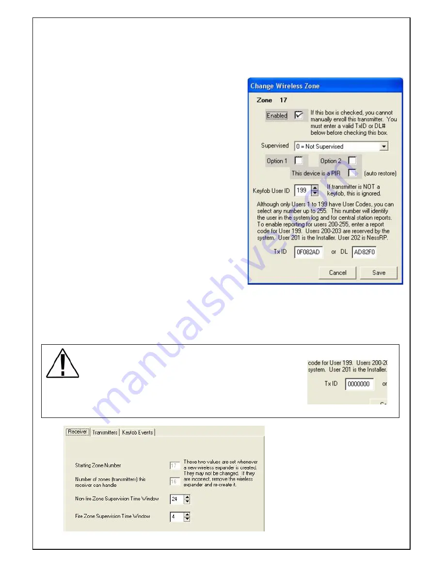
Enabled

 - Ensure this is ticked to enable the

                  Wireless Transmitter to be activated
                   by the M1 Control Panel.

Supervised 

- Select if you require the Zone to be

                        Supervised. (i.e. to activate an
                        alarm if no signal is received within
                        a selected time (e.g. 24 hours)
                       Only available with R15 PIR's and
                        RR1 Reed Switch's. Do not select on
                        for R12's or Feyfobs.

    Fire Zone Supervision is reserved for

                        future products.

Option 1 & Option 2

 - For future use. DO NOT

                    select these options or the wireless
                    signal may not be actioned by the M1.

This device is a PIR

 -

 This is selected if the device

                  learnt is a PIR where Auto Restores are
                  sent immediately.

Keyfob User ID

 - Only valid for Radio Keys (Keyfobs)

                       Select a user Code you wish the radio
                     key to be set to. This can be User 1-255
                     (excluding 200-203 as these are
                     reserved.)

Tx ID (or) DL

 -  This is the Radio Transmitters unique ID.

If this ID is known (e.g. learnt in and recorded from another "test" system) it can be manually
entered and downloaded into the M1 which will allow the transmitter to work.

To change setting in the transmitter settings, click on the Zone and then change.

Deleting Transmitters.

If a Radio Key is lost it can be deleted by replacing the Tx ID to all
Zero's, OR alternatively if a Radio detection devices needs to be
replaced then uncheck the "enabled" box which will allow a new
transmitter to be programmed in its place.

Supervision Times

Within the "receiver" Tab the Non-Fire
Supervision Time Window can be
adjusted. This is used if "Supervised  1=
Normal Supervision is selected".
Note Only available for R15 and Radio
Reeds.
Fire Zone Supervision is reserved for
future products.

Summary of Contents for M1RF

Page 1: ...Page 1 INSTALLATION MANUAL Ness M1RF Wireless Receiver Specifications Installation and Programming Ness Document No 895 364 Version 1 4 May 2008 ...

Page 2: ...the 4 Wire Data Bus DIP Switch Address Settings Flash Memory for Firmware Updating Status and Diagnostic LED On Board EOL Bus Termination Jumper Supplied in easy to mount equipment housing The Ness M1RF receiver is compatible with the following Wireless transmission devices at initial release Ness R15 PIR 100 663 Ness R15 PET 100 663PET Ness R12 PIR 100 691 Ness RR1 Radio Reed 100 662 Ness RR2 Uni...

Page 3: ...nes A B and provides a clean organized management of the data bus wires Data Bus E O L Termination is Very Important INSTALLATION AND ENROLLMENT OF NESS M1RF RECEIVER Select a suitable location for the receiver not within a metal cabinet with an ambient temperature range between 0 and 49 C 32 to 120 F The Ness M1RF Receiver connects onto the M1 data bus which uses 4 wires However CAT5 or CAT6 eigh...

Page 4: ...er module for the zone to be allocated for wireless Note You can add assign more than 16 zones of wireless on one wireless receiver by adding more wireless expanders and allocating more groups to wireless If the group is greyed out then those zones will already exist in this account Once zones have been allocated as Wireless Zones the Input module will be shown as a Wireless rather than a Input Ex...

Page 5: ... M1 voice is enabled not available on M1 EZ8 systems the system will provide voice prompts and feedback of enrolment If the voice prompt speaks Press Transmitter button for If the zone prompt does not speak a Voice description then it is will be because you have not entered one in for the Zone beingenroled Once enrolled the system will automatically move to learn mode of the next zone If a zone ha...

Page 6: ...tters have been learnt into the M1 their data can be uploaded to NessRP RIGHT mouse click on Wireless Setup and then select Receive Wireless Setup Once data has been received their Tx ID s can be viewed when wireless Transmitters tab is selected ...

Page 7: ...the radio key to be set to This can be User 1 255 excluding 200 203 as these are reserved Tx ID or DL This is the Radio Transmitters unique ID If this ID is known e g learnt in and recorded from another test system it can be manually entered and downloaded into the M1 which will allow the transmitter to work To change setting in the transmitter settings click on the Zone and then change Deleting T...

Page 8: ...etailed below to set buttons on each keyfob Ness Security Products Pty Ltd Sydney 02 8825 9222 Melbourne 03 9875 6400 Brisbane 07 3399 4910 Perth 08 9328 2511 Adelaide 08 8152 0000 email m1support ness com au Ness Document No 895 364 Programming Individual Buttons on Radio Keys each key Using rules programming within the M1 each button on each radio key can be programmed individually as the follow...

Reviews: