background image

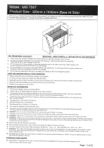
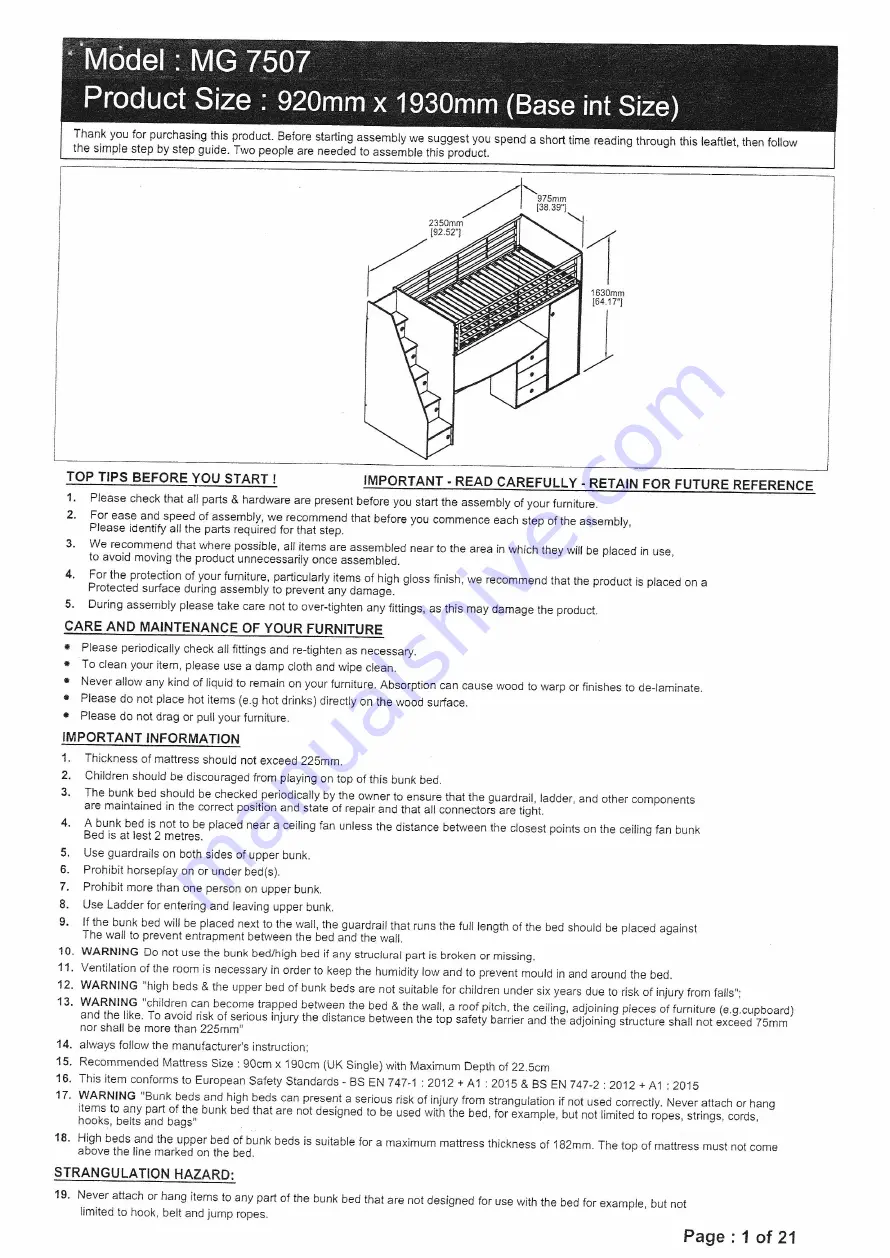
Summary of Contents for Dakota High Sleeper MG 7507
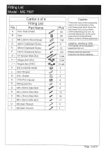
Page 1: ...on both sides of upper bunk 6 Prohibit horseplay on or under bed s 7 Prohibii more than one person on upper bunk 8 Use Ladder for entering and leaving upper bunk 9 lf the bunk bed will be placed next 10 the wall the guardrail that runs the full length of the bed should be placed against The wall to prevent enirapment between the bed and the wall 10 WARNING Do not use the bunk bed high bed if any s...

Page 2: ...LS TO ASSEMBLE THIS PRODUCT USE OF POWER TOOLS WILL INVALIDATE ANY CLAIM AND MAY DAMAGE TFIIS PRODUCT MAKING IT UNSAFE Phillips Screw Driver Approximately 2 hour 30 min 2 People Required Rubber Hammer Measure Page 2 of 21 ...

Page 3: ... Desk 1 29 Ladder Step 2nd Step 1 30 Left Panel 3rd Step 1 Carton 4 af 4 3i Right Panel 3rd Step 1 09 Support Panel Chest Drawers 2 32 Ladder Step 3rd Step 1 10 Bottom Panel Chest Drawers 1 33 Left Panel 4th Step 1 11 Left Panel Chest Drawers 1 34 Right Panel 4th Step 1 12 Right Panel Chest Drawers 1 43 Ladder Step 4th Step 1 L4 Back Panel Drawer 3 44 Left Panel 5th Step 1 15 Left Panel Drawer 3 4...

Page 4: ......

Page 5: ... Square Nut 4 O MB x 60mm Allen Bolt d 4 R M6 x 40mm Allen Bolt 10 S MO x 30mm Allen Bolt 32 T M6 x 25mm Allen Bolt 6 17 U MO Allen Wrench 2 2 V MB Allen Wrench 2 1 Caution There are many small components used in the construction of this unit These loose items should be kept away from young children whilst assembling your unit As an extra precaution screw cover caps should be permanently fixed in ...

Page 6: ... BxB C x 16 F xT Lx1 Hx3 1 A l I TIJ I t I I I WHEN FITTING CAMS ENSURE STARTING POSITION IS CORRECT BEFORE YOU INSERT CONNECTiNGBOLT TURN CLOCKWISE UNTIL SECURE l l f CORRECT L J bl FA WRONG Page 6 of 21 ...

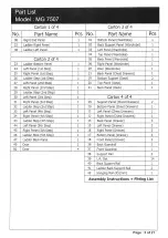
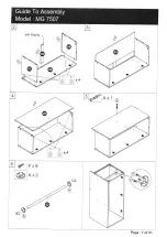
Page 7: ...I ffi with Edging g Fx6 Kx2 s lAt Page 7 of21 ...

Page 8: ...I I WHEN FITTING CAMS ENSURE STARTING POSITION IS CORRECT BEFORE YOU INSERT CONNECTING BOLT TURN CLOCKWISE UNTIL SECURE L l f CORRECT L l l AA WRONG To Assembly the Drawer Slide Please Follow Step as Belor r oo 0 oO o O o Page 8 ot21 ...

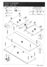
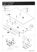
Page 9: ...Ax6 Bx3 Cx11 t7 1 I I r r t 1 Page 9 of 21 wiih Edging ...

Page 10: ...F x 16 J j Page 1A of 21 ...

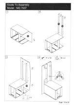
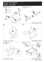
Page 11: ...Dx3 Tx3 1 Page 11 of 21 ...

Page 12: ...Tx5 r r Page 12 of 21 ...

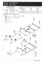
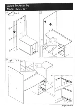
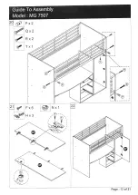
Page 13: ...Px2 Qx2 Rx2 Tx1 Fx6 Hx3 T 1 Nx1 O e s t 6 Page 13 of 21 ...

Page 14: ...x2 l iv j s iR ll q 1 l iry J v11 Do This Step 3 Times Nx3 F x12 Do This Step 3 Times Gx3sets i4l rh V6 Do This Step 3 Times re Do This Step 3 Times Page 14 of 21 Do This Step 3 Times ...

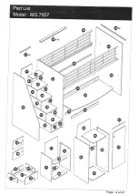
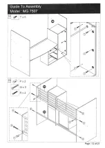
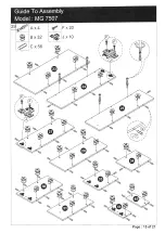
Page 15: ...Ax4 B x32 Cx56 Fx20 J x 10 9 M I I I I I I tt tu l br l 6 tg R Ll d Page 15 of21 ...

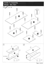
Page 16: ...A x 16 I I ll 1t 1 x4 d dl a I g t7 I x A i ri Page 16 of 21 with Edging ...

Page 17: ...with Edging g Page 17 of21 ...

Page 18: ...x2 a i Al i t F Iqt 8 i d x2 aa Y i lf l ie s i _ with Edging d t x2 a7 l l r P rft t ti I l r t Page 18 ot21 ...

Page 19: ...F x2A Jxlo w Page 19 of 21 ...

Page 20: ...Tx4 ts Rx4 Sx2 Page 24 of21 ...

Page 21: ...Page 21 of21 ...

Page 22: ...I iti es I irlrt r I i i r i I i lii I i i _ i Depth Adiustment after loosening the hinge arm mounting screw Latera I Adiustment by adjusting screw Vertica I Adiustment via mounting Plate via slots or if in two Pieces via screw ...

Reviews: