12
13
NC-1000 -
installation manual
12
13
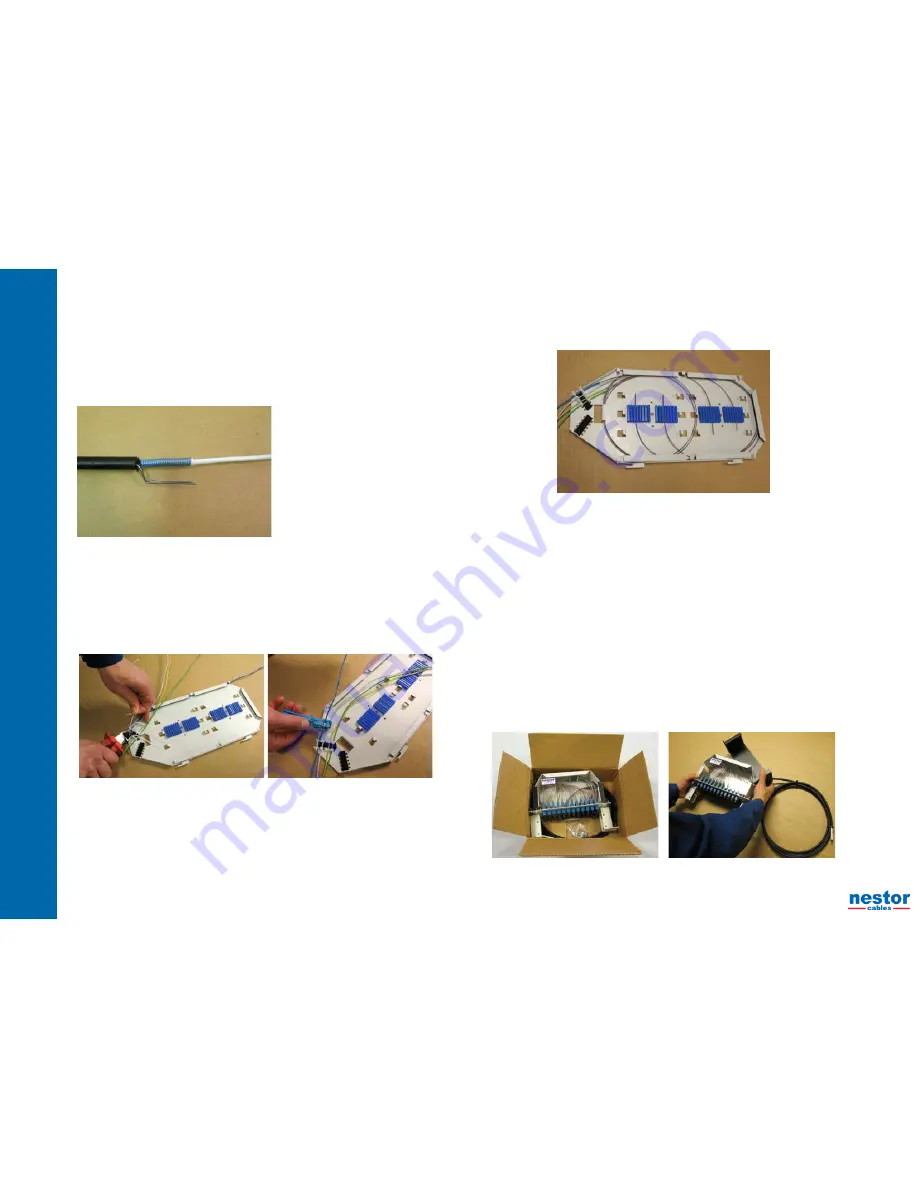
Clean the fibres from the filling compound.
•
Push the fan-out part of the installation kit (accessory) over the central tube and at the
•
same time guide the fibre bundles along their own slots of the fan-out part.
Fasten the fan-out part with the clamp to the end of the central tube. If the fastening is not
•
tight, use the small adjusting parts of the kit under the clamp.
Draw the bundled fibres into the protection tubes of the installation kit by using the pulling
•
wire included the kit. The minimum length of the tubes is 110 cm.
Push the protection tubes to the slots of the fan-out part and guide the fibres at the same
•
time directly from the central tube to the protection tubes.
Mark the ends of the protection tubes with numbers 1,2,…
•
5.1.4 Fibre entry to the splice tray
Remove the cover of the splice tray
•
Measure the fibre lenghts to the splice tray. If using Nestor NC-48 splice tray the fibre
•
lengths shall be about 120 cm.
Bring the ends of the fibre tubes to the left side of the splice tray (seen from the top) and
•
put them parallel so that the outermost tube is the first and innermost tube the last tube.
Fix the tubes with nylon ties.
•
If you are terminating stranded loose tube cable cut the tubes about 25 mm from the fixing
•
point and clean the tubes from the filling compound.
Loop the fibres to the splice tray. Loop each fibre bundle one full turn on the tray and take
•
each fibre bundle to its own splice holder from the left side Cut away the extra lengths of
fibres.
If you are using Nestor NC-48 splice tray, loop the fibres going to the two uppermost splice holders one
•
full turn around the tray and then to their splice holders from the left. The fibres going to two lowest
splice holders loop fibres first to other side of the tray from the halfway of the tray, then one full turn
around the tray and finally to their own splice holders from the right, see the picture below.
Make the appropriate markings on the splice tray.
•
Reattach the cover to the splice tray.
•
5.1.5 Installation of the splice trays to the splice tray holder
Draw the cable backwards to the back side of the frame so much that the cable sheath is outside of the
•
frame.
Fix the cable temporarily to the frame.
•
Install the splice tray into its appropriate position for waiting the splicing process.
•
Guide the fibre tubes below the splice trays on the hinge side of the inner frame to the back of the
•
frame.
The fibre tubes shall be positioned considering the following:
•
Bending radius of fibres
○
Movement of the inner frame
○
Possibility to remove each splice tray separately from the splice tray holder
○
5.1.6 Installation of NC-1000 patch panel
Open the panel package and lift the panel out from the package with its pigtail cable.
•
Take the basket nuts from the accessory kit and mount them to the right places of the inner frame.
•
Install the first panel of the frame into the highest place of the inner frame and the next panels under the
•
earlier panels.
Pull the panel frame out from the panel and fasten it to the inner frame from its lowest fixing holes.
•


