10
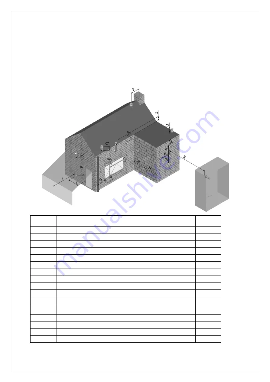
When the products of combustion are discharged, they should not cause a nuisance to adjoining or adjacent
properties and they should be positioned so that damage cannot occur to other parts of the building. If the outer
wall surface is constructed of combustible material, a non-combustible plate should be fitted behind the terminal
projecting 25mm beyond the external edges of the terminal.
Installation instructions
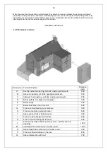
3.4.5 Terminal Locations.
Dimension Terminal Position
Distance
(mm)
A*
Directly below an opening, air brick, opening window etc.
600
B
Above an opening, air brick, opening window etc.
300
C
Adjacent to an opening, air brick, opening window etc.
400
D
Below gutters, soil pipes or drain pipes
300
E
Below eaves
300
F
Below balconies of car port roof
600
G
From a vertical drain pipe or soil pipe
300
H
From an internal or external corner
600
I
Above ground roof or balcony level
300
J
From a surface facing the terminal
600
K
From a terminal facing the terminal
600
L
From an opening in the car port (e.g. door , window into the
dwelling)
1200
M
Vertically from a terminal on the same wall
1500
N
Horizontally from a terminal on the same wall
300
P
From a vertical structure on the roof
600
Q
Above intersection with roof
150
Summary of Contents for C15
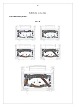
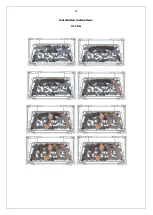
Page 13: ...13 Installation instructions 3 5 Fuel Bed Arrangements H15 LPG ...
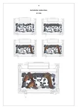
Page 14: ...14 Installation instructions H15 NG ...
Page 15: ...15 Installation instructions H25 LPG ...
Page 16: ...16 Installation instructions H25 NG ...
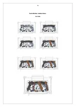
Page 17: ...17 Installation instructions H35 LPG ...
Page 18: ...18 Installation instructions H35 NG ...
Page 19: ...19 Installation instructions TQH35 LPG ...
Page 20: ...20 Installation instructions TQH35 NG ...
Page 21: ...21 Installation instructions H45 LPG ...
Page 22: ...22 Installation instructions H45 NG ...
Page 23: ...23 Installation instructions TQH15 LPG ...
Page 24: ...24 Installation instructions TQH15 NG ...
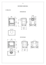
Page 25: ...25 Installation instructions 3 6 Dimensions H15 REAR FLUE H15 TOP FLUE ...
Page 26: ...26 Installation instructions S25 REAR FLUE S25 TOP FLUE ...
Page 27: ...27 Installation instructions S35 REAR FLUE S35 TOP FLUE ...
Page 28: ...28 Installation instructions RH35 REAR FLUE RH35 TOP FLUE ...
Page 29: ...29 Installation instructions H45 REAR FLUE H45 TOP FLUE ...
Page 30: ...30 Installation instructions TQH15 TOP FLUE ONLY ...
Page 31: ...31 Installation instructions TQH35 ...
Page 35: ...35 Technical Information Countries of destination types of gas ...

