32
Installation instructions
3.7 Commissioning the Appliance
3.7.1 Pilot Ignition Check
1.
Ignite the pilot light as described in the User Instructions
2.
Check that the pilot flame stays alight
3.
Extinguish the pilot light
3.7.2 Main Burner Check
1.
Ignite the pilot light as described in the User Instructions
2.
Turn on the main burner as described in the User Instructions
3.
Check that the pilot smoothly cross-lights to the main burner and that the main burner
and pilot stay alight
4.
Extinguish the appliance fully
3.7.3 Pressure Check
The appliance is preset to give the correct heat inputs as listed in the technical details. No
further adjustment is necessary. Always check the inlet pressure and burner pressure.
1.
Turn off the gas valve on the appliance
2.
Release the screw on the Inlet Pressure test point on the gas valve and connect a
manometer
3.
Check that the measured pressure is as the prescribed supply pressure
4.
Perform the test when the appliance is burning on full and with only the pilot alight
5.
If the pressure is low, check the gas supply pipes are too a correct sizing
6.
If the pressure is too high (more than 5 mbar over) the appliance may be installed,
but the gas supply company should be contacted
7.
Release the screw on the Burner Pressure test point on the gas valve and connect a
manometer
8.
Check that the measured pressure is as detailed in the Technical details
9.
The measured value should be /- 10% of the described value. If this is not the
case, please contact the supplier.
Note: After checking the pressures and removing the manometers, the screws in the
Pressure Test points must be closed, and the system must be checked for gas-tightness.
Summary of Contents for C15
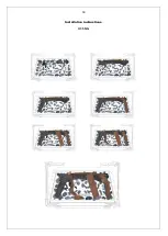
Page 13: ...13 Installation instructions 3 5 Fuel Bed Arrangements H15 LPG ...
Page 14: ...14 Installation instructions H15 NG ...
Page 15: ...15 Installation instructions H25 LPG ...
Page 16: ...16 Installation instructions H25 NG ...
Page 17: ...17 Installation instructions H35 LPG ...
Page 18: ...18 Installation instructions H35 NG ...
Page 19: ...19 Installation instructions TQH35 LPG ...
Page 20: ...20 Installation instructions TQH35 NG ...
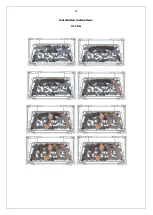
Page 21: ...21 Installation instructions H45 LPG ...
Page 22: ...22 Installation instructions H45 NG ...
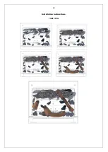
Page 23: ...23 Installation instructions TQH15 LPG ...
Page 24: ...24 Installation instructions TQH15 NG ...
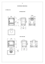
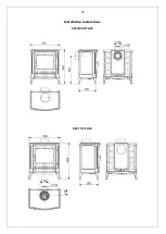
Page 25: ...25 Installation instructions 3 6 Dimensions H15 REAR FLUE H15 TOP FLUE ...
Page 26: ...26 Installation instructions S25 REAR FLUE S25 TOP FLUE ...
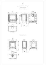
Page 27: ...27 Installation instructions S35 REAR FLUE S35 TOP FLUE ...
Page 28: ...28 Installation instructions RH35 REAR FLUE RH35 TOP FLUE ...
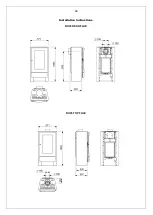
Page 29: ...29 Installation instructions H45 REAR FLUE H45 TOP FLUE ...
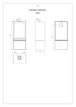
Page 30: ...30 Installation instructions TQH15 TOP FLUE ONLY ...
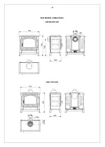
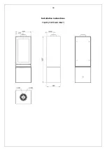
Page 31: ...31 Installation instructions TQH35 ...
Page 35: ...35 Technical Information Countries of destination types of gas ...

