background image


User instructions 

2.3 Batteries 

Remote Handset: 

1 x 9V "PP3" Battery, Quality alkaline recommended 

Receiver: 

4 x 1.5V "AA", Quality alkaline recommended for maximum life. 

An alternative AC Mains Adaptor may be used to power the Receiver instead of the 4 AA batteries. Only an AC 
Mains Adapter supplied by Nestor Martin may be used. The Mains Adaptor is plugged into the DC 6V socket on 
the end of the receiver. 

Note - if the AC Mains Adapter is used, remove the 4 AA's from the Receiver, failure to do so could result in 
damage and failure of the Receiver. During a period of power outage, the receiver may be unplugged and 
batteries returned to the Receiver. 

2.4 Replacing the batteries 

Handset: 

There is a battery level indicator on the display of the handset. When this gets low remove the cover on the rear 
of the handset and replace the battery with another 9V PP3 battery. 

Receiver: 

Three short audible beeps will sound when the appliance is on to indicate that the batteries in the receiver are 
getting low. 

When the batteries get very low the appliance will be turned off by the remote control. This will fail to happen if 
the power supply is interrupted. 

To replace the Receiver batteries, slide the cover off of the top of the receiver and use the ribbon to pull the 
batteries out. Replace the batteries with new 1.5V AA's, ensuring that the ribbon is located under the batteries 
and that the polarity is correct on all 4 batteries. 

Never mix new batteries with old, this will result in the new batteries being emptied very quickly. 

When the batteries are replaced, it may be necessary to reset the transmitter code, as detailed in the next 
section. 

2.5 Setting the Transmitter code 

Press and hold the RESET button with a sharp object (pen or screwdriver) until you hear two audible beeps. After 
the second, longer beep, release the RESET button. 

Within the next twenty seconds press the down button (Button D fig 1.1) on the remote handset until you hear an 
additional long signal confirming the code is set.  

2.6 To Ignite the appliance 

Note - If this appliance is extinguished or goes out in use for any reason, wait 3 minutes before attempting to 
relight the appliance. The Gas Control Valve has an interlock device which will not allow relighting until the 3 
minutes have passed. 

To be able to use the Remote control Handset (fig. 1.1), the rocker switch on the Gas Valve, must be turned "ON" 
(the "1" position) and the manual Dial set to the "On" position. 


Simultaneously press and hold buttons B & C (Star and Large Flame), until a short acoustic 

beep confirms the start sequence has begun; release the buttons. 


Continuing signals confirm the ignition is in process. 


Once pilot ignition is confirmed, there will be gas flow and the main burner will ignite. 


Repeat process if pilot ignition fails. 


Summary of Contents for C15

Page 1: ...S S15 AND C15 H45 ALSO KNOWN AS S45 AND C45 RH35 ALSO KNOW AS FH35 H25 ALSO KNOWN AS S25 AND C25 H35 ALSO KNOWN AS S35 AND C35 TQH15 Models H15 ALSO KNOWN AS S15 S15 AND C15 H45 ALSO KNOWN AS S45 S45 AND C45 TQH35 ALSO KNOW AS FH35 AND RH35 H25 ALSO KNOWN AS S25 S25 AND C25 H35 ALSO KNOWN AS S35 S35 AND C35 TQH15 ...

Page 2: ... setting 6 2 9 N A 6 2 10 Setting C 24 hour or F 12 hour clock 6 2 11 Setting the Time 6 2 12 Cleaning and Maintenance 6 3 Installation instructions 7 3 1 Gas Connection 7 3 2 Ventilation 7 3 3 Installation 7 3 4 Flue Connection 8 3 5 Fuel Bed Arrangements 13 3 6 Dimensions 24 3 7 Commissioning the appliance 30 4 Servicing 32 4 1 Cleaning the Ceramics 32 4 2 Servicing the Burners 32 4 3 Spare part...

Page 3: ...rate this appliance if the glass panel has been broken or cracked removed or is open The appliance is designed to fit numerous installation situations as listed in these installation instructions However only flue approved by Nestor Martin for this appliance may be used This appliance is a balanced flue product and is room sealed and as such requires no additional ventilation for operation However...

Page 4: ...ld recommend opening windows if possible Run the appliance at full setting for a few hours so that the paint gets an opportunity to fully cure During this period it is possible for some fumes and vapours to be given off We would recommend keeping children and pets out of the area at this time 2 2 Remote Control Overview This Nestor Martin Gas Appliance has been constructed with an advanced remote ...

Page 5: ...lace the batteries with new 1 5V AA s ensuring that the ribbon is located under the batteries and that the polarity is correct on all 4 batteries Never mix new batteries with old this will result in the new batteries being emptied very quickly When the batteries are replaced it may be necessary to reset the transmitter code as detailed in the next section 2 5 Setting the Transmitter code Press and...

Page 6: ... Simultaneously pressing the Large Flame Button and Small Flame Button buttons C D fig 1 1 Press the Large Flame button button C fig 1 1 to set the hour Press the Small Flame button button D fig 1 1 to set the minutes Press OFF button B fig 1 1 to return to standard operating mode or simply wait and it will return to standard mode after approximately 15 seconds 2 12 Cleaning and Maintenance This a...

Page 7: ...re connected to the Burner of the appliance Fine adjustment and leveling legs is available via the feet Do not make any adjustments to the appliance The appliance and Flue system should be fitted with a minimum clearance of 500mm from any combustible objects or materials this includes any combustible materials used for the fireplace construction As this is a room sealed appliance and the appliance...

Page 8: ...0mm from any combustible materials A combustible shelf may be fitted over the appliance if in the case of a 150mm or less deep shelf there is at least 280mm clearance above the top of the stove The shelf depth may increase at the same rate as the increase in clearance i e a shelf depth of 200mm would require a clearance of 330mm 280 min ...

Page 9: ...er Frame Construction Whilst it is possible to install room sealed appliances in timber frame properties great care needs to be taken to ensure that the flue assembly does not interfere with the weather proofing qualities of any outer wall which it may penetrate Before attempting this work further details need to be referenced e g Gas Installations in Timber Frame Buildings from the Gas Safe insta...

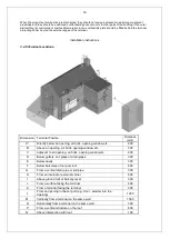
Page 10: ...air brick opening window etc 600 B Above an opening air brick opening window etc 300 C Adjacent to an opening air brick opening window etc 400 D Below gutters soil pipes or drain pipes 300 E Below eaves 300 F Below balconies of car port roof 600 G From a vertical drain pipe or soil pipe 300 H From an internal or external corner 600 I Above ground roof or balcony level 300 J From a surface facing t...

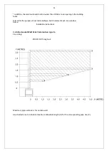
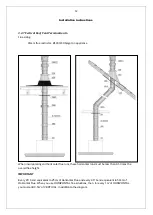
Page 11: ...for outside wall Use shaded area to calculate maximum allowable length H for the corresponding pipe rise V I addition the terminal should not be nearer than 300mm to an opening in the building fabric formed for the purpose of accommodating a built in element such as a window frame Installation instructions ...

Page 12: ...ing and horizontal flue runs these horizontal runs must be less than 0 5 times the overall flue height IMPORTANT Every 45 bend equivalent to 25cm of Horizontal Flue and every 90 bend equivalent to 50cm of Horizontal Flue When you use HORIZONTAL flue situations then for every 1m of HORIZONTAL you must add 0 5m of VERTICAL in addition to the diagram ...

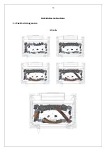
Page 13: ...13 Installation instructions 3 5 Fuel Bed Arrangements H15 LPG ...

Page 14: ...14 Installation instructions H15 NG ...

Page 15: ...15 Installation instructions H25 LPG ...

Page 16: ...16 Installation instructions H25 NG ...

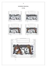
Page 17: ...17 Installation instructions H35 LPG ...

Page 18: ...18 Installation instructions H35 NG ...

Page 19: ...19 Installation instructions TQH35 LPG ...

Page 20: ...20 Installation instructions TQH35 NG ...

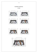
Page 21: ...21 Installation instructions H45 LPG ...

Page 22: ...22 Installation instructions H45 NG ...

Page 23: ...23 Installation instructions TQH15 LPG ...

Page 24: ...24 Installation instructions TQH15 NG ...

Page 25: ...25 Installation instructions 3 6 Dimensions H15 REAR FLUE H15 TOP FLUE ...

Page 26: ...26 Installation instructions S25 REAR FLUE S25 TOP FLUE ...

Page 27: ...27 Installation instructions S35 REAR FLUE S35 TOP FLUE ...

Page 28: ...28 Installation instructions RH35 REAR FLUE RH35 TOP FLUE ...

Page 29: ...29 Installation instructions H45 REAR FLUE H45 TOP FLUE ...

Page 30: ...30 Installation instructions TQH15 TOP FLUE ONLY ...

Page 31: ...31 Installation instructions TQH35 ...

Page 32: ... valve on the appliance 2 Release the screw on the Inlet Pressure test point on the gas valve and connect a manometer 3 Check that the measured pressure is as the prescribed supply pressure 4 Perform the test when the appliance is burning on full and with only the pilot alight 5 If the pressure is low check the gas supply pipes are too a correct sizing 6 If the pressure is too high more than 5 mba...

Page 33: ...ressures L Check the safe operation of the appliance 4 1 Cleaning the Ceramics Remove the ceramics as detailed in A B above Gently clean the ceramics in the open air using a soft brush and a vacuum cleaner Where necessary replace damaged components only with genuine Nestor Martin specified parts Seal any scrap ceramics in plastic bags and dispose at proper refuse sites When using a vacuum cleaner ...

Page 34: ...34 Servicing 4 3 Spare parts For spare parts contact Nestor Martin quoting the name and part number of the appliance and the type of spare part you require ...

Page 35: ...35 Technical Information Countries of destination types of gas ...

Page 36: ...15 22 16 22 28 9 28 9 36 29 Injector Marking 480 560 480 160 180 Pilot 446 0330 24 446 0330 44 Efficiency Class 1 Nox Class 5 H25 Gas type G20 G20 G25 G20 G25 G25 G30 G31 G31 I2H I2E I2E I2ELL I2 I3B P 30 50 I3 I3P 37 50 I3P 30 Supply Pressure mbar 20 20 25 20 25 30 50 28 30 37 37 50 30 Nominal Heat Input Gross Hs kW 9 9 9 9 7 8 7 8 7 8 7 8 Nominal Heat Input Nett Hi kW 8 1 8 1 8 1 8 1 7 2 7 2 7 2...

Page 37: ... 2 28 8 28 8 36 29 Injector Marking 1200 220 260 Pilot 446 0330 24 446 0330 44 Efficiency Class 1 Nox Class 5 S45 Gas type G20 G20 G25 G20 G25 G25 G30 G31 G31 I2H I2E I2E I2ELL I2 I3B P 30 50 I3 I3P 37 50 I3P 30 Supply Pressure mbar 20 20 25 20 25 30 50 28 30 37 37 50 30 Nominal Heat Input Gross Hs kW 11 6 11 6 11 6 11 6 9 8 9 8 9 8 9 8 Nominal Heat Input Nett Hi kW 10 5 10 5 10 5 10 5 9 0 9 0 9 0...

Page 38: ...13 13 13 27 5 27 5 35 29 Injector Marking 1200 260 280 Pilot 446 0330 24 446 0330 44 Efficiency Class 1 Nox Class 5 TQHI5 Gas type G20 G20 G25 G20 G25 G25 G30 G31 G31 I2H I2E I2E I2ELL I2 I3B P 30 50 I3 I3P 37 50 I3P 30 Supply Pressure mbar 20 20 25 20 25 30 50 28 30 37 37 50 30 Nominal Heat Input Gross Hs kW 9 5 9 5 9 5 9 5 8 8 8 8 Nominal Heat Input Nett Hi kW 8 6 8 6 8 6 8 6 7 4 7 4 7 4 7 4 Con...

Reviews: