7
Installation instructions
3. Installation instructions.
Before commencing Installation, confirm that the details on the appliance data plate correspond to the local
distribution conditions, gas type and pressure to which the appliance is to be installed.
Ensure that gas supply and supply pipe is capable of delivering the required volume and pressure of gas and is in
accordance with the rules in force.
3.1 Gas Connection
This appliance has a gas inlet connection of Ø 8mm or Ø 12mm dependant on country of use
3.2 Ventilation
This appliance is a Balanced Flue room sealed appliance, and as such needs no additional ventilation. However
an adequate supply of fresh air to maintain temperatures and a comfortable environment is recommended.
This appliance may be installed in a completely sealed or mechanically ventilated house.
3.3 Appliance Fireplace Installation (INSET)
Determine the position required for the appliance.
Create a gas connection for the appliance in approximately the correct location for the gas controls.
The gas controls are connected to the Burner of the appliance.
Fine adjustment and leveling legs is available via the feet.
Do not make any adjustments to the appliance.
The appliance and Flue system should be fitted with a minimum clearance of 500mm from any combustible
objects or materials; this includes any combustible materials used for the fireplace construction.
As this is a room sealed appliance and the appliance stands on appropriate feet, a hearth is not required for this
appliance.
The Fireplace should be ventilated with openings giving a total free vent area of 200 cm².
A gap of 50mm should be left all round the appliance (applies to non-combustible surfaces only).
3.4 Appliance installation (Models SHC15, SHC45, RH35 and FH35, SHC25, SHC35, TQH15 and TQH35)
3.5 A non-combustible hearth must be used this hearth must be a minimum of 12mm thick, and project a
minimum of 50mm from the base of the appliance in all directions.
3.6
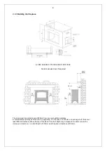
These appliance are not suitable for installation against a combustible wall. A combustible side wall must be a
minimum of 75mm from the appliance. (see page 8)
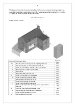
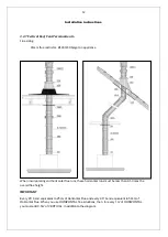
3.7 These appliances can be installed with an up and out flue (vertical wall - horizontal flue) except TQH15 (only
vertical flue) .
Specific terminals are mandatory, see page 9
Summary of Contents for C15
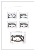
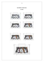
Page 13: ...13 Installation instructions 3 5 Fuel Bed Arrangements H15 LPG ...
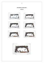
Page 14: ...14 Installation instructions H15 NG ...
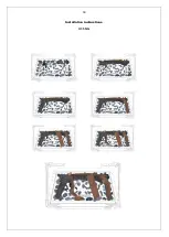
Page 15: ...15 Installation instructions H25 LPG ...
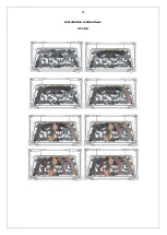
Page 16: ...16 Installation instructions H25 NG ...
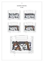
Page 17: ...17 Installation instructions H35 LPG ...
Page 18: ...18 Installation instructions H35 NG ...
Page 19: ...19 Installation instructions TQH35 LPG ...
Page 20: ...20 Installation instructions TQH35 NG ...
Page 21: ...21 Installation instructions H45 LPG ...
Page 22: ...22 Installation instructions H45 NG ...
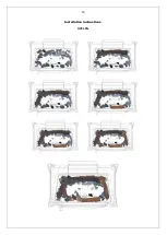
Page 23: ...23 Installation instructions TQH15 LPG ...
Page 24: ...24 Installation instructions TQH15 NG ...
Page 25: ...25 Installation instructions 3 6 Dimensions H15 REAR FLUE H15 TOP FLUE ...
Page 26: ...26 Installation instructions S25 REAR FLUE S25 TOP FLUE ...
Page 27: ...27 Installation instructions S35 REAR FLUE S35 TOP FLUE ...
Page 28: ...28 Installation instructions RH35 REAR FLUE RH35 TOP FLUE ...
Page 29: ...29 Installation instructions H45 REAR FLUE H45 TOP FLUE ...
Page 30: ...30 Installation instructions TQH15 TOP FLUE ONLY ...
Page 31: ...31 Installation instructions TQH35 ...
Page 35: ...35 Technical Information Countries of destination types of gas ...

