

44
INSTALLATION INSTRUCTIONS
Standard Installation
1. Position the unit no closer than the minimum clearances to combustible materials (see page
40). Check that no overhead cross members in the ceiling or roof will be cut. Reposition unit if
necessary, being careful not to move closer than the minimum clearances.
2. Position the unit on the floor at the proper clearances.
3. Install a steel connector pipe on the flue collar of the unit.
4. The stove is NOT to be connected to any air distribution duct or system. A chimney connector
shall not pass through an attic or roof space, closet or similar concealed space, or a floor, or
ceiling. Use a chimney connector adapter to connect the chimney connector up to the
chimney. The small ends of the chimney connector should all point down for a drip-free
installation. Position all seams toward the back for aesthetics.
5. Check that all clearances are still within the allowable tolerances.
6. Secure adjoining sections of chimney connector to each other using three equally spaced
sheet metal screws. Secure the connector pipe to flue collar using three equally spaced sheet
metal screws. DO NOT secure chimney connector to chimney with screws.
DO NOT CONNECT THIS UNIT TO A CHIMNEY FLUE SERVING ANOTHER APPLIANCE.
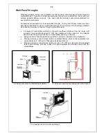
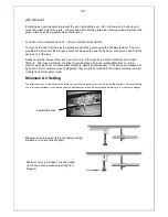
Freestanding Installations
If the chimney connector must pass through a combustible wall to reach the chimney, follow the
recommendations in the Wall Pass-Through section that follows.
The openin
g through the chimney wall to the flue (the “breach”) must be lined with either a
ceramic or metal cylinder, called a “thimble”, which is securely cemented in place. Most
chimney breeches incorporate thimbles, but the fit must be snug and the joint between the
thimble and the wall must be cemented firmly.
A special piece called the “thimble sleeve”, slightly smaller in diameter than standard
connectors and most thimbles, will facilitate the removal of the chimney connector system for
inspection and cleaning. Thimble sleeves are available from your local dealer.
To install a thimble sleeve, slide it into the breech until it is flush with the inner flue wall. Do not
extend it into the actual flue passage, as it could interfere with the draft.
The thimble sleeve should protrude 1-
2” (25-50 mm) into the room. User fire cement and thin
gasketing to seal the sleeve in place in the thimble. Secure the chimney connector to the outer
end of the sleeve with sheet metal screws.
Above a Fireplace
In this type of installation, the chimney connector rises from the stove, turns 90°, and then goes
into the fireplace chimney. The liner of the fireplace chimney should extend at least to the point
at which the chimney connector enters the chimney. Follow all the guidelines for installing a
chimney connector into a freestanding masonry chimney, and pay special attention to these
additional points:
Double check the connector clearance from the ceiling: 18” (45 cm) minimum.
The fireplace damper must be closed and sealed to prevent room air from being drawn
up the flue, thereby reducing the draft. However, it must be possible to re-open the damper to
inspect the chimney.
Summary of Contents for H33
Page 2: ...2 ...
Page 4: ...4 BELGIE NEDERLAND GEBRUIKSAANWIJZING HOUT MULTI ...
Page 17: ...17 BELGIQUE FRANCE MODE D EMPLOI BOIS MULTI ...
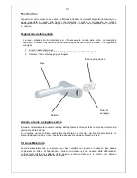
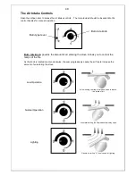
Page 19: ...19 FONCTIONNEMENT Fonctionnement des commandes ...
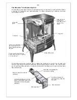
Page 27: ...27 WOODBOX TECHNOLOGY ISTRUZIONI PER L USO STUFE A LEGNA MULTICOMBUSTIBILE ...
Page 41: ...41 WOOD STOVES WOODBOX TECHNOLOGY INSTALLATION AND OPERATING INSTRUCTIONS ...
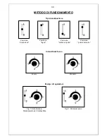
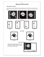
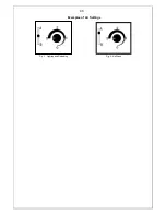
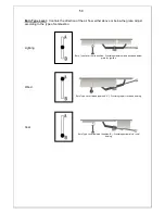
Page 48: ...48 Examples of Air Settings Fig 1 Lighting and Reloading Fig 2 Air Wash ...
Page 60: ...60 ESTUFAS DE LEÑA WOODBOX TECHNOLOGY MANUAL DE INSTRUCCIONES ...
Page 79: ...79 ...
Page 80: ...80 ...
Page 81: ...81 ...
Page 82: ...82 ...
Page 83: ...83 ...
Page 84: ...84 ...
Page 85: ...85 ...
Page 86: ...86 ...
Page 87: ...87 ...
Page 88: ...88 SOTO DE LA MARINA CANTABRIA Apdo de correos 208 SANTANDER C07100DA003_3 01 2016 ...


