background image


66

User Manual

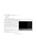
   4.10.3  Alarm Status

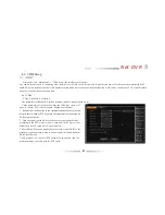
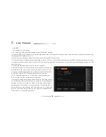
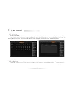
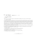
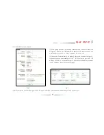
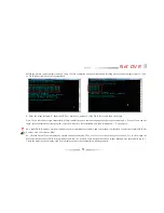
      The interface is as follows:

      It shows the alrm type of each channel: Sensor alarm (Red color), motion alarm(Yellow color) and video lost alarm(Blue color). You can clear

the  alarm through the 

CLEAR

  button of the front  panel or remote controlleror  click the 

alarm clear

 on the  menu by  mouse.

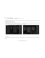
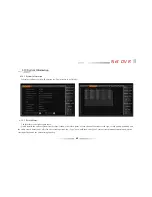
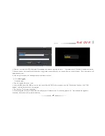
   4.10.4  Online Status

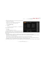
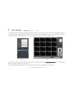
      It displays the information of outer PC which connected to DVR. Such as: IP address, login/off time.The interface is the right figure above:

Summary of Contents for DVR7004

Page 1: ...d it will work the difference between product function and operation It is for reference only We will not provide any new information separately for later firmware update The updating files will be added into the new edition of the user manual and will also be posted on our website in the download center This user manual may have some inaccuracy or misprint We sincerely hope your timely feedback a...

Page 2: ... Chapter 3 Equipment Installation and Illustration 14 3 1 Installation Environment and Cautions 14 3 1 1 Attentions on Installing Hard Disk 16 3 2 Package Checking 16 3 3 The Back Panel Instructions of DVR 17 3 3 1 The Back Panel Chart 17 3 3 2 Video Audio Connection 19 3 3 3 USB Backup Interface 19 3 3 4 Network Interface 19 3 3 5 Alarm Input Output Connection 19 3 3 6 RS 485 RXConnection 24 3 3 ...

Page 3: ...Menu Operation Description 32 3 7 1 Menu Structure Chart 32 3 7 2 Menu Option Schedule 33 Chapter 4 Device Operation 38 4 1 Power On 0ff and Login Lock 38 4 1 1 Keystroke Unlock Lock 38 4 1 2 System Login 39 4 1 3 System Lock 39 4 1 4 Main Menu 39 4 2 General Setup 40 4 2 1 General Setup 40 4 2 2 Time Setup 41 4 3 Record Setup 42 4 3 1 Record Parameter 42 4 3 2 Manual Record 43 4 3 3 Schedule Reco...

Page 4: ...om 48 4 5 2 Sensor Alarm Setup 51 4 5 3 Alarm Output 52 4 5 4 Email Setup 52 4 6 COM Setup 53 4 6 1 COM 53 4 6 2 PTZ 54 4 7 Network Setup 55 4 7 1 IP Setup 55 4 7 2 DDNS 56 4 7 3 PPPOE 57 4 8 Playback 58 4 9 System Management 59 4 9 1 User Management 59 4 9 2 Backup Management 61 4 9 3 Disk Management 62 4 9 4 Restore Default 63 4 9 5 Password Reset 64 ...

Page 5: ...arm Status 66 4 10 4 Online Status 66 4 10 5 Log Information 67 4 11 Software Upgrade 68 4 11 1 Client Software Upgrade 68 4 11 2 USB Upgrade 69 4 12 Power Resume 70 Appendix 1 IE Operation Instructions 71 1 LAN Configuration for IE Browse 71 2 WAN Operation Instructions 72 Appendix 2 Net DVR Q A 75 ...

Page 6: ...ingle board This series DVR achieve the integrate host to a single plate structure which ensure the system s high integration and reliability DVR7000 series adopt latest file system which named MFS it s the latest file system which is based on the Microsoft FAT32 It is the innovative and dedicated DVR file system It won t create the disk defragment in a long run Logical stream media operation fast...

Page 7: ...annel 1 channel 1 channel 1 channel 1 channel Voice chat support support support support support support HDD port SATAx1 SATAx1 SATAx2 SATAx2 SATAx1 SATAx1 Alarm input 4 channels 4 channels 8 channels 8 channels 8 channels 8 channels Alarm output 2 channels 2 channels 2 channels 2 channels 2 channels 2 channels Loop video support support support support support support Multi playback 4 channels 4 ...

Page 8: ...t 1 channel 1 channel 1 channel 1 channel Voice chat support support support support HDD port SATAx2 SATAx2 SATAx2 SATAx2 Alarm input 16 channels 16 channels 24 channels 24channels Alarm output 2 channels 2 channels 2 channels 2 channels Loop video support support support support Multi playback 16 channels 16 channels 16 channels 16 channels DVD Burner support support support support Backup interf...

Page 9: ...nput resistance 10K Ω input extent Vp p 2 0VLINEin 50mVMICin 3 Video compression Compression arithmetic H 264 Resolution CIF PAL 352x288 25FPS NTSC 352x240 30FPS 4 Audio Compression Compression arithmetic G 711A Audio sampling rate 8K sample sec 16 bit sample 5 Operation System Real Time Operation System RTOS 6 HDD interface 1SATA interfaces support 48bit LBA working mode 7 Alarm interface Alarm i...

Page 10: ... we have series products and different hardware and software versions u Compression features 1 Support PAL NTSC video format signal 2 Video compression algorithm is H 264 3 Video and audio signals are compressed into H 264 code stream Audio and video stream are synchronous when playback and audio recording can be canceled if only video is in need 4 Audio compression algorithm adopt G 711A the vide...

Page 11: ...rameters of each camera can be set up separately 7 Support OSD such as channel name record time date week etc 8 Support multiplex operation can real time recording without impacting other functions such as playback fast forward slow playback rewind network monitor VOD and remote download when displaying the record files at the same time 9 Support pre record feature and pre record time is 0 30 seco...

Page 12: ...m format The recording file can be recognized on the PC and played by our player u Alarm inspection functions 1 Local alarm video lost alarm motion detection alarm sensor alarm no HDD alarm no HDD space alarm video abnormal alarm HDD sector error alarm 2 Remote alarm video lost alarm motion detection alarm and sensor alarm can be sent to client manager via network 3 Video lost alarm motion detecti...

Page 13: ...grade u Security guarantee 1 High quality 32 bits embedded microprocessor and embedded RTOS which ensure the system s high affectivity reliability and stability 2 Perfect log search function sensor record log motion detection record log remote login log record parameter modification log update log playback log system start up log backup log 3 System lock keystroke lock password verification multi ...

Page 14: ...ion or on using Avoid installing in high temperature or humidity conditions Heat release fans are placed for cool down so you should put the device on ventilated place The back of Net DVR should be placed 6cm away from the other device or wall while installing Moving the Net DVR between two places with high difference in temperature will shorten the using life Please install the lightning conducto...

Page 15: ...plug or draw when the power is on or else the equipment will be easily damaged Use the power on off button on the front panel instead of direct shut off the power directly when turn off the Net DVR so that the hard disk won t be damaged After installation machine can automatically detect hard disk If an unformatted hard disk is detected system will give off information whether to format the disk F...

Page 16: ...bout 15MB per camera per hour In order to save HDD space we suggest closing the audio except users mandatory require audio recording If you choose CBR recording the recording data will not differ from the bit rate option Notes When HDD is full the default set will let system overwrite the earliest recorded files and the free space will show 0M 4 The attachments such as data cable power line and ha...

Page 17: ...17 Net DVR 3 3 The Back Panel Instructions of DVR 3 3 1 The Back Panel Chart DVR7008M DVR7016 ...

Page 18: ...menu output AUDIO IN Connect audio input standard BNC interface AUDIO OUT Connect audio devices localaudio signaloutput VGA Connect VGA MIC Connect mike for voice intercommunication USB Connect USB backup files ETHERNET Connect Ethernet device such as HUB ALARM RS 485 Connect RS 485 12V DCPOWER ChooseACvoltage220V 110Vthrough switch ON OFF Power supply switch ...

Page 19: ...ernet interface which is used to connect the PC and the DVR The indicator lights ACT and LINK are used to indicate current network status LINK Network speed indicator on 100M off 10M ACT Send Receive data indicator Blink Sending Receiving data Notes When you directly connect the computer s network card with the host DVR please use the cross line when connect with the computer through router please...

Page 20: ...ut The physical connections of the normal on off mode are the same And user can select normal on off mode in the DVR Typical alarm connection the sensor power supply is provided by DVR The fig is as follows DVR Sensor 12V GND Input 1 Input 2 NO NC C ...

Page 21: ...21 Net DVR If the distance between the probe and DVR is too far the probe requires a separate power supply NO NC C DVR 12V GND Input 1 Input 2 12V power supply Sensor ...

Page 22: ...User Manual If we parallel connected the sensor the DVR can not recognize the triggered sensor User need to have a resistance DVR Sensor 1 12V GND Input 1 Input 2 C NO NC Sensor 3 C NO NC Sensor 2 C NO NC ...

Page 23: ...vidual power supply Alarm Output1A Output1B DVR supply the power separately Normally Alarm s power usually is much bigger preferably supply power separately and do not use the DVR s power to supply Each series alarm output critical parameters are as follows 240V AC7A 125V AC10A 28V DC10A Exceeding these parameters will damage the motherboard ...

Page 24: ...rd we suggest user using one series keyboard to control more than one DVR in the same model The function of the keyboard is the same with the remote controller Note the keyboard must be added with the protocol from our company and go through the test of our company Take the RS485 interface series keyboard for example Attentions for PTZ decoder connection 1 Confirm that the PTZ decoder and Net DVR ...

Page 25: ...25 Net DVR 3 4 Front Panel Description 3 4 1 Front Panel and Layout Description ...

Page 26: ...al time display 2 It means zoom under PTZ control status Video format Zoom 1 Shift between single and division video when in real time display or playback 2 It means zoom under PTZ control status Image Iris 1 Set the parameters of each channel 2 It means iris when in PTZ control Clear Iris 1 Edit delete 2 Alarm clear 3 It means iris when in PTZ control Up Focus 1 Menu up 2 It means focus when in P...

Page 27: ...ndication lamp it is light when there is alarm or it will be off REC Record indication lamp it is blink when DVR is recording or it will be off NET Network connection indication lamp it is light when the PC client connect to the DVR Slow play 1 Cursor move 2 Slow play 3 It means up while in PTZ control Frame on 1 Cursor move 2 Frame on 3 It means down while in PTZ control Rewind 1 Cursor move 2 Re...

Page 28: ...ate input left click the mouse you can see the software keyboard After input date right click the mouse you can exit the software keyboard Left click the mouse 1 Left click the mouse and you will enter the functional menu 2 In the main menu left click and choose the item to enter or set up the parameters 3 When selecting the motion detection setup left click the mouse to change the status of the m...

Page 29: ...uble click left mouse the division can be switched by double click Double click left mouse in the input box to enable the software keyboard right click the mouse to exit software keyboard The interface is as follows ...

Page 30: ...30 User Manual 3 6 IR Remote Control ...

Page 31: ...formation 30 PTZ 5 Playback 18 Backup 31 Server Index 6 Fast Forward 19 Image Iris 32 2ABC 7 OK Play Pause 20 Shift Zoom 33 1 8 Return 21 Clear Iris 34 5JKL 9 F2 22 Format Zoom 35 4GHI 10 Auto 23 Record 36 8TUV 11 Wiper 24 Up Slow Motion 37 7PQRS 12 3DEF 25 Left Backward 38 0 13 6MNO 26 Down Frame Forward 39 Preset Note F1 and F2 are preserved functional keys ...

Page 32: ...32 User Manual 3 7 Menu Operation Description 3 7 1 Menu Structure Chart ...

Page 33: ...olution 800 X 600 1024X768 1280X1024 1440X900 6 Language switching Support in both Chinese and English switching Time setup Set systemdate time Record setup Schedule record Set continuous record time table Record parameters 1 Record type manual schedule motion detection and alarmrecord 2 Definition CIF D1 3 Bitrate type CBR VBR 4 Bit rate size 100K 128K 256K 512K 1M 1 5M 2M 3M 4M Under the CIF max...

Page 34: ...up Display Setup 1 Setting channel name 2 Video mask area 3 Channel duplication 4 Date format setup year month day month day year 5 OSD setup channel name time week temperature 6 Video parameters setup brightness transparence contrast Hue 7 Video input adjustment Sequence Setup Sequencesetup Sequencecruise channels polling interval sequence cruise type Video Matrix Video matrix setup support 1 1 o...

Page 35: ...5 Channel duplication Sensor Detection 1 Sensor ID 2 Alarm schedule 3 Relate the recording channel 4 Recall PTZ preset position 5 Channel duplication Alarm Output 1 Full screen when alarm output 2 Buzzer alarm output 3 Alarm retain time 0 300 s 4 Alarm type normal on off 5 Alarm recording time 6 Alarm output duplication Email Setup Support email alarm upload ...

Page 36: ...d delete user account 2 Change local remote user account and authority Support remote user authorities remote preview parameter setup remote playback remote backup log Inquiry voice talk remote upgrade user binding IP and MAC address Backup Setup Support backup require playback the record date Hard Disk Management Display the status information of each HDD HDD format Restore to Default Restore to ...

Page 37: ... address connected channel Log Information Require system log display number of log Menu of Right Click the Mouse Main Menu Enter the main menu rapidly Image Switch Switch the channel rapidly Video Zoom Enter the real time digital zoom menu rapidly PTZ Enter the PTZ menu rapidly Alarm Clear Alarm Clear Video Parameters Video parameter adjustment brightness contrast saturation Hue Logout Logout Shu...

Page 38: ...we specially set the key lock and unlock function for the machine 4 1 1 Keystroke Unlock Lock When multi DVRs are put to work together using the remote controller may influence the machines which users do not intend to control So we set system key lock function correspond to remote control Under the system management of DVR main menu please enter series configuration and setup device number then e...

Page 39: ...se the figure of login will appear as follows Input user name and password on the login port distribute in authority in advance after you input correct user name and password and press ENTER the sign on the lower left corner will switch to automatically and show the current user name Then you can carry on the operations in the authority to the system at the moment 1 Default user admin default pass...

Page 40: ...t 4 2 General Setup 4 2 1 General Setup l Overwrite We suggest that user select auto overwrite mode when disk is full the DVR will auto overwrite the earliest recording file The alarm indicate method When HDD is full GUI information indicates whether overwrite the earliest recording files and stop the recording l Auto locking When you enable auto locking system will enter the status of locking in ...

Page 41: ...m time on general occasion l Network time checking NTP NTP Network Time Protocol means regulate the time form remote server via network The default sever is hk pool ntp org port 123 time zone is GMT 08 00 Make sure select NTP before use this function 1 The system support 26 time zone for setting user can set according to current zone 2 We do not suggest user change the Time server on general occas...

Page 42: ...nstant even when image source changes The characteristic for CBR is in limited bitrate to have good compression images as well as easy to estimate the HDD occupation and network bandwidth 4 3 1 Record Parameter Before using the record function it is important to setting the record parameter It is related to video playback and hard disk capacity etc After login select record setup record parameter ...

Page 43: ...or sub stream The net stream parameter setting affect network sub stream l Pre record time The 4 record modes support Pre record function default pre record time is 10s range is 0 30s Due to the variable bitrate the actual pre record time may have some difference with what your set l Delay record time The record duration time when the motion sensor alarm appears default duration time is 30s range ...

Page 44: ... deployment period 3 Set the alarm deployment period system supports setting multi periods Time period should be selected in chronological order Tick off the date and then enable the time period By dragging the left mouse to set the deployment period Note double click left mouse can cancel one selected time period 4 Click save to activate the settings you can also duplicate the settings to other c...

Page 45: ...area will shown 1 Channel Name l The channel name can be established at most 16 Chinese characters or 32 English letter and numeral l Modify by mouse Double click left button to pop out the software keyboard In the pinyin input states click En to switch to English input method l Modify by remote controller Use to switch the input method l Channel name fixed fold on the top left corner of the corre...

Page 46: ...h channels user can also setup all channels directly Adjustment Method 1 Select the parameters you want to change then press button on the remote controller 2 Click the left mouse on the to change the value the on the interface can indicate the increase or decrease of the value 3 Video input adjustment Video input adjustment adjust black edges on each channel The input video is normally with black...

Page 47: ...No sequence division sequence interval time The interface is as follows l Sequence format 1ch 4ch 9ch divisions l Sequence channel number user can set the sequence channel number the sequence channel number must be more than the selected division l Sequence interval time range is 3 60s Note The sequence function is only enable in system locking status ...

Page 48: ...vity of the motion detection is adjustable and the sensitivity goes up in order from 1 to 5 When the motion detection of the current channel happens the system will alarm and record If the sensitivity is low such as 1 when the video scene make a big change the system will motion detection alarm If the sensitivity is high such as 5 when the video scene make little change the system will motion dete...

Page 49: ...wise the button is grey 2 Video Lost Alarm The DVR default enable alarm output when video lost We provide three ways to output alarm audio buzzer full screen You can press information button to enter alarm information status rapidly 4 5 2 Sensor Alarm Setup The steps of sensor alarm setup is as follows 1 After login choose main menu Record setup record parameter to enter the setting interface of a...

Page 50: ...ting procedure is as follows 1 Click PTZ preset point to enter the PTZ preset interface then you can set the preset point Note the range of the PTZ preset is 1 255 255 means close when copying the channel parameters these settings will not copied to other channels After finishing this operation you should right click mouse to enter the up menu and click save to activate the setting 2 In COM Setup ...

Page 51: ...put deployment time l Sensor type normal on off l Alarm to full screen when the system is in multi picture and the alarm is triggered the alarm channel will auto full screen l Alarm to buzzer when the alarm is triggered the system will start buzzing l Audio alarm when the alarm is triggered the alarm sound will output to the audio output l Alarm output time inspection 2 300s the system default is ...

Page 52: ...he sender email 5 Input the receiver mail box which can be multiple and separated by the maximum length of the letter you input is 256 bit 6 Default port is 25 nomally do not need to change 7 Set the e mail upload interval time that is the time interval for upload alarm information to the target email no matter how many times alarm triggered it just upload once during every interval time and also ...

Page 53: ...nel l Baudrate Set the baudrate of the communication between COM and its outer devices Such as PTZ keyboard s baudrate must be identical with DVR system s baudrate l Data bit stop bit check bit Set the data bit stop bit and check bit according to the PTZ protocol code Commonly the PTZ protocol s default date bit is 8 check bit is None stop bit is 1 l Host address When one keyboard connect with sev...

Page 54: ...d calling preset point by the remote controller Enter the PTZ status press the direction button make the PTZ turn the direction which you want to set as preset point press preset botton on remote controller and input the No of the preset point in the box such as 001 then turn the PTZ to another direction if you press the call button and input the No 1 which you preset to the box the PTZ will turn ...

Page 55: ... 255 means closed l Disable DHCP If there is no DHCP service in the LAN you can choose this option to designate the static IP address IP settings This IP must be unique It can t conflict with the IP of other servers or working stations in the same LAN Default 192 168 0 6 Subnet mask code Used to differentiate subnet Gateway address Used to realize communication between different networks it needs ...

Page 56: ...y Note You must connect the net manually after first set the auto re dial 4 7 2 DDNS Our DVR system support DDNS function You can analyze the WAN IP which is directly dial form the ADSL and also the router mapping WAN IP address This function supports the domain name which is registered from www oray cn www dyndns com You can choose one of them according to the need l Login www oray cn to apply th...

Page 57: ...nd press Connect to connect the WAN l Auto Connect If you select this option system will automatically connect the WAN after disconnection l Save password If you select this option system will automatically save the ADSL password so you don t need to input them again when reconnect to the WAN l It shows the network information of the public network such as IP Subnet address after the connection su...

Page 58: ...l After choose time period and channel system will update the record data l When you choose a record file the start stop time and size of the file will display at the lower part of the interface l Move cursor to the file you want by remote controller press confirm button to start playback the file you can also use this function by double left click mouse on the file l Click page up down key for ca...

Page 59: ...ld modify the password on the User management interface l Right click the mouse during playback to use hide playback control menu l Support digital zoom when playback by mouse Operation procedure Enter the playback image click mouse wheel to start option left click mouse for selecting digital zoom start point then drag mouse to the point where you want to be digital zoom end point There will be ap...

Page 60: ... remote rights setting l Display the user list when login When login the DVR use the on the remote controller or click the wheel of the mouse to select the user If not select Display the user list when login you must input the username when login 2 User Group Support user group function each user can just take part in one group the admin user can distribute rights to users in this group The interf...

Page 61: ...manual 2 U disk backup suppot U disk hot swappable The backup disk must be FAT32 and capacity is bigger than 512M 3 Support CD DVD burnner 1 File Backup The backup interface is the right figure above Backup function allows to backup up to 26 record files for different channels or different time periods The details of backup is as follows 1 Input time period and channel number ...

Page 62: ...ckup file playback To playback the backup files user has to enter the backup interface and click Inquire button select the record file and press ENTER to playback Backup date Display the backup files in current HDD backup partition Move the cursor on the date icon and press ENTER and the file list at the right side would display all files information of the date Backup file list Display backup fil...

Page 63: ...the format icon and press OK to choose the type of the partition DATA or BACKUP The interface is as follows after you confirmed the partition type press OK the system will prompt It s formatting lock time 3 minutes Date format YYYY MM DD Display channel name Enabled Display time Enabled Display temperature Enabled Channel switch Closed Rec Para Record mode All Encoding stream type VBR Encoding str...

Page 64: ...ase lid from the machine 3 Find J1 it s on top right of the SCM which is beset on the back of the front panel 4 Jump the thread piece to put the legs 1 2 next to the resistance R13 of J1 to the status of short circuit the thread piece is put on the legs 2 3 when leave factory 5 Connect the power supply and start the machine You can hear buzzer sounds and it indicates that the passwords have been s...

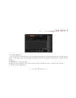
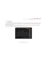
Page 65: ...terface is the right figure above Quick inquire the current system record status It shows the record status of each channel s current record type record quality definition and the audio record status on or off if in the recording status the Type bar would show the type of current record manual timer motion alarm record quality shows the current image quality ...

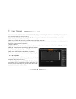
Page 66: ...m Yellow color and video lost alarm Blue color You can clear the alarm through the CLEAR button of the front panel or remote controlleror click the alarm clear on the menu by mouse 4 10 4 Online Status It displays the information of outer PC which connected to DVR Such as IP address login off time The interface is the right figure above ...

Page 67: ...ited The log file can t be recognized on PC the log information of host side can search and show through client software Click page up down key for category search in different pages l Contents of the logbook system start up shutdown and change version log alarm log PTZ control log user login log off changing system parameters recording playback log backup log format HDD log user login client log ...

Page 68: ... have any doubts don t upgrade or in case you fail to upgrade the firmware you can neither redo the system upgrade nor restart the machine These upgrade failure machine must send back to the factory Ø After upgrade for the new features please refer to the user manual of the new version You can get the new version from our website or the suppliers Ø Don t modify the software including the name of t...

Page 69: ...em restart the admin password is the former version s 4 11 2 USB Upgrade Operation steps 1 Copy the upgrade bin to the U disk 2 Insert the USB flash to the USB port on the back panel after the USB device recognized enter the information interface click USB upgrade and confirm the hints to start upgrade 3 The host says The system is updating 4 When the upgrade have been finished the host will pops ...

Page 70: ...12 Power Resume If the power is shut down unexpectedly when the system is in standby or working status system could start automatically restart and resume to the original status after power back The advantage of this function assures the system maintain the continuity condition for outage ...

Page 71: ...re may not run properly Please guarantee to install DirectX 9 0 of Microsoft and confirm the Internet Explorer edition is 6 0 version or above 1 LAN Configuration for IE Browse 1 Ping the host IP first to confirm if the DVR is connected 2 Type the host IP into windows IE and connect to the DVR Input user name and password to log in If the log in is succeeded the following interface will pop out ...

Page 72: ...ess in windows IE and visit the host through network 2 WAN Operation Instructions If you want to connect multiple DVRs to wide area network with only one IP please refer to the following instruction Firstly set up IP subnet mask and gateway in the IP set up interface of network setting in the main menu of host DVR Note Gateway must be set the same as the mapping router s LAN IP After set up connec...

Page 73: ... 143 163 2 Choose the Transfer Rules on Figure 2 left menu as shown in Figure 3 respectively input command port 8101 HTTP monitor port 80 IP Address 192 168 2 6 as shown in Figure 1 and choose to enable the agreement ALL Click the Save to save the settings Fig 2 Fig 3 Take the TP LINK as an example 3 Port Description The command port is the TCP port of all DVRs communications and HTTP port is IE b...

Page 74: ... name and port number the punctuation must be input Fig 4 Fig 5 a When the two ports are default setting directly input the WAN IP address 116 30 143 163 shown in Figure 2 into client manager and sign in After login successfully the interface is shown as Figure 4 For IE browse directly input the WAN IP address 116 30 143 163 shown in Figure 2 and input the correct user name and password you can lo...

Page 75: ...correct operation If you can not make sure the problems please run Reset default option A The problem about rebooting self testing system halted 01 Why the DVR doesn t start up though power cable is well connected to power source 01 1 Check if you have turned on the switcher on the back panel 2 Check if you have inputted the right power password and pressed Enter button 02 I see the Super DVR logo...

Page 76: ...been damaged 2 Check if the front panel is in lock up status If so press Login Lock button and input power password to unlock 3 Please check if the host software locks the operation If yes please input user name password to login so to make IR remoter control work 06 Why system halts at some certain time 06 In case system halts at some certain time for example around 7 30am please check your elect...

Page 77: ...ed color 05 1 Please check you VGA data line as well as connection condition between DVR to VGA monitor 2 Check if the DVR system has overheat 06 I started my system seeming to be successfull but there was a certain channel displaying nothing neither caption Why 06 Please make restore to factory default settings 07 Why it displays mosaics when playback 07 1 Check the recording parameter setting If...

Page 78: ...data may lose in transmission which will cause mosaics 2 Check the DVR server side if the original images have mosaics 3 On win2003 operating system after the successfully sign if DVR client cannot open image or images have mosaics please set as the following On the desktop space click the right button of mouse and select Attribute Settings High FAQ hardware acceleration option completely 02 How t...

Page 79: ...lease uninstall the client program select new directory for installation and then implement A F steps again 06 I input DVR IP address user name and password in client manager software and system shows successfully connected to remote DVR but I cannot view the cameras Why 06 1 Please check if the computer has opened firewall protection If so close it or set the security level lower 2 Try to close o...

Page 80: ...tion detection record 04 1 Please check the motion detection record schedule setting There are two periods The first one shall be ahead of the second one 2 Please check if you have correctly selected the motion detection areas 3 Maybe caused by too low sensitivity Try to increase the motion detection sensitivity 05 Why cannot I make alarm record 05 1 Please check the alarm record schedule setting ...

Page 81: ...ng during live view or playback 11 Check the format of DVR and cameras system Make sure they are in same format PAL or NTSC 10 Why playback is quite slow 10 1 Please check whether you choose the slow playback Our DVRs support 1 2 1 4 1 8 1 16 of the slow speed 2 Please check whether the hard cable is connected well meanwhile check whether there is a damage to the sector of hard disk When there is ...

Page 82: ...please patiently test whether your PTZ or high speed dome protocols can be used in our DVRs 02 How to connect multiple PTZ cameras or PTZ devices 02 1 Please make connection in star method Connect multiple controlling lines RS485 in parallel connection and set addresses properly 2 Bus connection Connect 485 and 485 to the DVR s 485 and 485 pins and connect the next DVR s 485 and 485 to the first D...

Page 83: ...83 Net DVR NOTES SDVR Build20110105 ...

Reviews: