Net
Safety
Monitoring
Inc.
24
MAN-0047 Rev 12 MLP-A/AR/AD-SC1100 & MLP- LP-A/AR/ARS-SC1100
All relays have normally open and normally closed contacts
available at the output terminals.
The Fault relay is set for normally energized operation and is non-
latching. If a system fault is detected, the Fault relay becomes de-
energized. The Fault relay is factory set and cannot be altered. The
Low alarm and High alarm relays can be selected for either normally
energized or normally de-energized operation and latching or non-
latching.
An optional low power Solid State relay board comes with Form A
contacts rated 2.5 Amps at 60 VAC/DC and selectable energized/de-
energized, latching/ non-latching configurable low and high alarms.
Fault relay is factory set as energized, non-latching and cannot be
modified.
Modbus
Digital RS-485 Modbus RTU protocol is used.
Register 40001 = LEL output (read only)
Register 40002 = Status (read only)
Register 40101 = Reset latched alarms (write)
Note
: Many registers are used by the controller. Please do not write
outside the registers.
Current
A 4-20 mA dc current output is used to transmit the alarm status and
fault codes to other devices. This output can be wired for isolated or
non-isolated operation. A 4.0 mA output indicates normal operation;
> 4.0 < 20.0 mA output indicates the presence of gas. Current output
of 2.5 mA indicates the presence of a system fault.
SECTION 7: Maintain
Periodic Response Check
We recommend the Millennium be verified or calibrated every 3
months. A typical response check involves the application of
calibration gas to the sensor, then the observation of the response
LEDs, Analog output, display and external monitoring equipment.
Be sure to prevent unwanted response of external monitoring devices
and equipment during this procedure. If the Millennium response to
calibration gas is within its specified accuracy then it is not necessary
to perform a calibration. For example, when 50% of full scale is
applied, the response is expected to be between 11.5 mA (47% of
full scale) and 12.5 mA (53% of full scale). An additional
consideration is the accuracy and tolerance of the calibration gas
which may be + or - a few percent. If the calibration gas is + or -
10% of full scale then the reading may be from 10.7 mA (42% of full
scale) to 13.3 mA (58% of full scale).
Troubleshoot
Response to the input should be checked and, if necessary,
calibration should be performed whenever any of the following
occur. Refer to "Calibration Procedure” for calibration instructions.
•
Excess negative drift is indicated by 2.5 mA current output.
•
Sensor or transmitter is connected or disconnected.
•
Long term or high concentration exposure to gas.
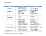
See “Table 6: Troubleshooting guide” for assistance in
troubleshooting. Also refer to “How to Return Equipment”, if
returning equipment.
Repairs to Net Safety products should not be performed in the field.
Repairs to faulty or damaged equipment should only be performed at
the factory; otherwise warranty on the product will be voided.

