1.4 Connect the E1 Line(s)
1.4.1 Local Connection
1.4.1.1 Select the Appropriate RJ21 Connector(s)
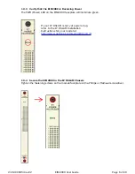
E1 cables must be connected according to the IP DSLAM slot in which the EIM2000 was
installed. In previous illustrations the EIM2000 was installed in Slot 3, therefore the E1
cable(s) should be plugged into the third RJ21 connector(s) from the right.
1.4.1.1.1 IPD12000E or IPD4000E
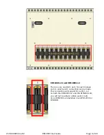
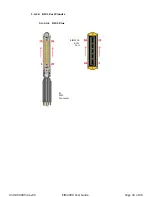
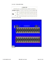
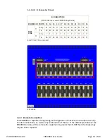
Each interface module slot on the IPD12000E and IPD4000E has two [2]
corresponding RJ21 connectors located on the back of the chassis. The bottom
row of RJ21 connectors (A) on the IPD12000E provides the E1 connection for
EIM2000 ports 1-12 and the top row of RJ21 connectors (B) provides the E1
connection for EIM2000 ports 13-24. On the IPD4000E, the A connectors for each
interface module slot are on the left and the B connectors are on the right.
N
OTE
The EIM2000-24 utilizes both rows of RJ21 connectors on the IPD12000E and IPD4000E.
The EIM2000-12 utilizes only the A connectors on the IPD12000E (lower row) and
IPD4000E (left-hand side).
210-0000054 rev0
2
EIM2000 User Guide Page 7 of 20


