220-0000073 rev01
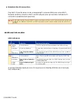
4. Establish the E3 connection.
Plug the E3 Tx and Rx cables into the corresponding E3 connection BNC ports on the UIM-E3
faceplate. Verify the connection; the E3 Lnk LED will pulse (once per second) to indicate the E3
connection is established and operational.
Additional Information
LED Indicators
(A pulsing LED blinks steadily at a rate of once per second. A flashing LED blinks at a more rapid,
less constant rate.)
NOTE
An E3 Uplink Interface Module (UIM-E3) must be connected via E3 line to an E3 network extender provider unit
(ENE3400-P or ENE3400-P-6-AC/DC). A UIM-E3 connected to an E3 network extender subscriber unit will not
function.
LED State
Indication
Additional Information
Lnk
flashing
green
E3 is operational
The E3 connection has been established and traffic is flowing.
solid green
E3 link is established
A connection exists but there is indication of a problem with the E3
line.
no
illumination
Loss of Synchronization
(LOS)
The incoming connection to the UIM-E3 has been lost; no data is
being received.
Alm
no
illumination
E3 is operational
Note: If the E3 Lnk LED also remains unlit then the UIM-E3 has
LOS.
solid amber
Remote Alarm Indication
(RAI)
The outgoing connection from the UIM-E3 has been lost; no data
is being transmitted.
pulsing
amber
Alarm Indication Signal
(AIS)
An indirect connection has been lost; the UIM-E3 may no longer
be receiving data.


