background image

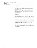
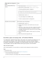
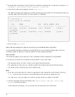
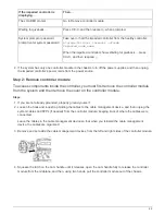
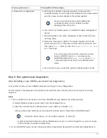
If the impaired controller is
displaying…

Then…

The LOADER prompt

Go to Remove controller module.

Waiting for giveback…

Press Ctrl-C, and then respond 

y

 when prompted.

System prompt or password
prompt (enter system password)

Take over or halt the impaired controller from the healthy controller:

storage failover takeover -ofnode

impaired_node_name

When the impaired controller shows Waiting for giveback…, press
Ctrl-C, and then respond 

y

.

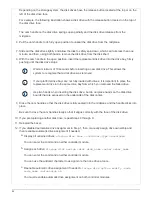
4. If the system has only one controller module in the chassis, turn off the power supplies, and then unplug

the impaired controller’s power cords from the power source.

Step 2: Remove controller module

To access components inside the controller, you must first remove the controller module
from the system and then remove the cover on the controller module.

Steps

1. If you are not already grounded, properly ground yourself.

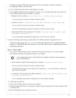
2. Loosen the hook and loop strap binding the cables to the cable management device, and then unplug the

system cables and SFPs (if needed) from the controller module, keeping track of where the cables were
connected.

Leave the cables in the cable management device so that when you reinstall the cable management
device, the cables are organized.

3. Remove and set aside the cable management devices from the left and right sides of the controller module.

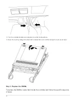
4. Squeeze the latch on the cam handle until it releases, open the cam handle fully to release the controller

module from the midplane, and then, using two hands, pull the controller module out of the chassis.

69

Summary of Contents for AFF A220

Page 1: ...in ONTAP Systems NetApp June 27 2022 This PDF was generated from https docs netapp com us en ontap systems fas2700 bootmedia replace overview html on June 27 2022 Always check docs netapp com for the...

Page 2: ...220 and FAS2700 21 Chassis 31 Controller 42 Replace a DIMM AFF A220 and FAS2700 68 Replace SSD Drive or HDD Drive AFF A220 and FAS2700 79 Replace the NVMEM battery AFF A220 and FAS2700 83 Swap out a p...

Page 3: ...steps on the correct node The impaired node is the node on which you are performing maintenance The healthy node is the HA partner of the impaired node Check onboard encryption keys AFF A220 and FAS27...

Page 4: ...hether the system has either NetApp Volume Encryption NVE or NetApp Storage Encryption NSE enabled If so you need to verify the configuration Steps 1 Connect the console cable to the impaired controll...

Page 5: ...need it in disaster scenarios where you might need to manually recover OKM Return to admin mode set priv admin Shut down the impaired controller b If the Restored column displays anything other than y...

Page 6: ...anager key show detail a If the Restored column displays yes manually back up the onboard key management information Go to advanced privilege mode and enter y when prompted to continue set priv advanc...

Page 7: ...t down the impaired controller Verify NVE configuration 1 Display the key IDs of the authentication keys that are stored on the key management servers security key manager key query After the ONTAP 9...

Page 8: ...b Verify the Restored column shows yes for all authentication keys security key manager key query c Verify that the Key Manager type shows onboard and then manually back up the OKM information d Go t...

Page 9: ...You can safely shut down the controller 2 If the Key Manager type displays external and the Restored column displays anything other than yes a Enter the onboard security key manager sync command secu...

Page 10: ...and then respond y when prompted System prompt or password prompt enter system password Take over or halt the impaired controller from the healthy controller storage failover takeover ofnode impaired...

Page 11: ...red controller is displaying Then The LOADER prompt Go to Remove controller module Waiting for giveback Press Ctrl C and then respond y when prompted System prompt or password prompt enter system pass...

Page 12: ...until it releases open the cam handle fully to release the controller module from the midplane and then using two hands pull the controller module out of the chassis 5 Turn the controller module over...

Page 13: ...ate the boot media in the controller and follow the directions to replace it Steps 1 If you are not already grounded properly ground yourself 2 Locate the boot media using the following illustration o...

Page 14: ...ng 7 Close the controller module cover Step 3 Transfer the boot image to the boot media You can install the system image to the replacement boot media using a USB flash drive with the image installed...

Page 15: ...sing Ctrl C when you see Starting AUTOBOOT press Ctrl C to abort If you miss this message press Ctrl C select the option to boot to Maintenance mode and then halt the controller to boot to LOADER 6 Fo...

Page 16: ...level set privilege advanced c Run the restore backup command system node restore backup node local target address impaired_node_IP_address d Return the controller to admin level set privilege admin...

Page 17: ...mand 10 Move the console cable to the repaired controller and run the version v command to check the ONTAP versions 11 Restore automatic giveback if you disabled it by using the storage failover modif...

Page 18: ...ed Paste the output of security key manager backup show OR security key manager onboard show backup command The data is output from either security key manager backup show or security key manager onbo...

Page 19: ...e and CFO style data aggregates will be shown 12 Move the console cable to the target controller 13 If you are running ONTAP 9 5 and earlier run the key manager setup wizard a Start the wizard using t...

Page 20: ...e console displays Then The login prompt Go to Step 7 Waiting for giveback a Log into the partner controller b Confirm the target controller is ready for giveback with the storage failover show comman...

Page 21: ...ll nodes from all available key management servers Check the output of the security key manager query again to ensure that the Restored column yes and all key managers report in an available state 11...

Page 22: ...3 minutes and check the failover status with the storage failover show command 6 At the clustershell prompt enter the net int show is home false command to list the logical interfaces that are not on...

Page 23: ...degradation You must replace the failed component with a replacement FRU component you received from your provider Step 1 Shut down the impaired controller To shut down the impaired controller you mu...

Page 24: ...system system node halt impaired_node_name 4 If the system has only one controller module in the chassis turn off the power supplies and then unplug the impaired controller s power cords from the pow...

Page 25: ...e the controller module from the midplane and then using two hands pull the controller module out of the chassis 5 Turn the controller module over and place it on a flat stable surface 6 Open the cove...

Page 26: ...module you are installing It must support the caching capacity All other components in the storage system must be functioning properly if not you must contact technical support Steps 1 If you are not...

Page 27: ...it into the chassis Steps 1 If you are not already grounded properly ground yourself 2 If you have not already done so replace the cover on the controller module 3 Align the end of the controller mod...

Page 28: ...into the chassis to avoid damaging the connectors The controller begins to boot as soon as it is seated in the chassis b If you have not already done so reinstall the cable management device c Bind th...

Page 29: ...er halt and then at the LOADER prompt enter boot_ontap press Ctrl C when prompted and then boot to Maintenance mode e From the boot menu select the option for Maintenance mode Step 5 Run system level...

Page 30: ...s tests Then Were completed without any failures a Clear the status logs sldiag device clearstatus b Verify that the log was cleared sldiag device status The following default response is displayed SL...

Page 31: ...ompted to get to the Boot menu If you have two controller modules in the chassis fully seat the controller module you are servicing in the chassis The controller module boots up when fully seated If y...

Page 32: ...urviving cluster 5 Verify that the switchback operation has completed metrocluster show The switchback operation is still running when a cluster is in the waiting for switchback state cluster_B metroc...

Page 33: ...ure is disruptive For a two controller cluster you will have a complete service outage and a partial outage in a multi node cluster Shut down the controllers AFF A220 and FAS2700 Shut down or take ove...

Page 34: ...ding on your system if the NVMEM NVRAM LED is flashing there is content in the NVMEM NVRAM that has not been saved to disk You need to reboot the controller and start from the beginning of this proced...

Page 35: ...e over or halt the impaired controller from the healthy controller storage failover takeover ofnode impaired_node_name When the impaired controller shows Waiting for giveback press Ctrl C and then res...

Page 36: ...it to the power supply using the power cable locking mechanism Only connect the power cable to the power supply Do not connect the power cable to a power source at this time Step 2 Remove the control...

Page 37: ...sis The drive should disengage from the chassis allowing it to slide free of the chassis When removing a drive always use two hands to support its weight Drives are fragile Handle them as little as po...

Page 38: ...rack or system cabinet using the screws you removed from the old chassis 7 If you have not already done so install the bezel Step 5 Install the controller After you install the controller module and a...

Page 39: ...the controller module into the chassis to avoid damaging the connectors b If you have not already done so reinstall the cable management device c Bind the cables to the cable management device with t...

Page 40: ...system 4 The next step depends on your system configuration If your system is in Then A stand alone configuration a Exit Maintenance mode halt b Go to Completing the replacement process An HA pair wi...

Page 41: ...ics tests from the Maintenance mode prompt sldiag device modify dev interconnect sel enable The interconnect tests are disabled by default and must be enabled to run separately 5 Run the interconnect...

Page 42: ...both controllers at the LOADER prompt bye e Return the controller to normal operation If your system is running ONTAP Then With two nodes in the cluster Issue these commands node cluster ha modify co...

Page 43: ...you can perform the MetroCluster switchback operation This returns the configuration to its normal operating state with the sync source storage virtual machines SVMs on the formerly impaired site now...

Page 44: ...part to NetApp Return the failed part to NetApp as described in the RMA instructions shipped with the kit See the Part Return Replacements page for further information Controller Overview of controll...

Page 45: ...can troubleshoot any issues that you might encounter during the replacement process Shut down the impaired controller AFF A220 and FAS2700 To shut down the impaired controller you must determine the s...

Page 46: ...iting for giveback press Ctrl C and then respond y Replace the controller module hardware AFF A220 and FAS2700 To replace the controller module hardware you must remove the impaired controller move FR...

Page 47: ...e until it releases open the cam handle fully to release the controller module from the midplane and then using two hands pull the controller module out of the chassis 6 Turn the controller module ove...

Page 48: ...ule and then check the NVRAM LED identified by the NV icon The NVRAM LED blinks while destaging contents to the flash memory when you halt the system After the destage is complete the LED turns off If...

Page 49: ...attery holder 7 Position the battery pack by aligning the battery holder key ribs to the V notches on the sheet metal side wall 8 Slide the battery pack down along the sheet metal side wall until the...

Page 50: ...e the DIMMs To move the DIMMs you must follow the directions to locate and move them from the old controller module into the replacement controller module You must have the new controller module ready...

Page 51: ...te the NVMEM battery plug socket and then squeeze the clip on the face of the battery cable plug to insert it into the socket Make sure that the plug locks down onto the controller module Step 5 Move...

Page 52: ...into the socket 5 Reseat and push the heatsink down to engage the locking button on the caching module housing 6 Close the controller module cover as needed Step 6 Install the controller After you ins...

Page 53: ...round yourself 2 If you have not already done so replace the cover on the controller module 3 Align the end of the controller module with the opening in the chassis and then gently push the controller...

Page 54: ...e hook and loop strap d Interrupt the boot process only after determining the correct timing You must look for an Automatic firmware update console message If the update message appears do not press C...

Page 55: ...ppears do not press Ctrl C to interrupt the boot process until after you see a message confirming that the update is complete Only press Ctrl C after you see the Press Ctrl C for Boot Menu message If...

Page 56: ...he replacement node is not at the LOADER prompt halt the system to the LOADER prompt 2 On the healthy node check the system time show date The date and time are given in GMT 3 At the LOADER prompt che...

Page 57: ...tem level diagnostics to function properly boot_diags During the boot process you can safely respond y to the prompts until the Maintenance mode prompt appears 3 Display and note the available devices...

Page 58: ...sts that you want to run sldiag device modify dev dev_name selection only selection only disables all other tests that you do not want to run for the device d Run the selected tests sldiag device run...

Page 59: ...to run for the device d Verify that the tests were modified sldiag device show e Repeat these substeps for each device that you want to run concurrently f Run diagnostics on all of the devices sldiag...

Page 60: ...e components are properly installed in the storage system d Reconnect the power supplies and then power on the storage system e Rerun the system level diagnostics test Recable the system and reassign...

Page 61: ...stems in a two node MetroCluster configuration Option 1 Verify the system ID change on an HA system You must confirm the system ID change when you boot the replacement controller and then verify that...

Page 62: ...privilege admin 5 Give back the controller a From the healthy controller give back the replaced controller s storage storage failover giveback ofnode replacement_node_name The replacement controller...

Page 63: ...ms that are in a stand alone configuration Steps 1 If you have not already done so reboot the replacement node interrupt the boot process by pressing Ctrl C and then select the option to boot to Maint...

Page 64: ...ks to the new controller s system ID before you return the system to normal operating condition About this task This procedure applies only to systems in a two node MetroCluster configuration running...

Page 65: ...reassign s old system ID In the case of the preceding example the command is disk reassign s 118073209 You can respond Y when prompted to continue 5 Verify that the disks or FlexArray LUNs were assig...

Page 66: ...de show fields configuration state node1_siteA metrocluster node show fields configuration state dr group id cluster node configuration state 1 node1_siteA node1mcc 001 configured 1 node1_siteA node1m...

Page 67: ...ures on the node might put you out of compliance with your license agreement so you should install the replacement license key or keys on the replacement node as soon as possible Before you begin The...

Page 68: ...network interface show is home false If any LIFs are listed as false revert them to their home ports network interface revert 2 Register the system serial number with NetApp Support If AutoSupport is...

Page 69: ...urviving cluster 5 Verify that the switchback operation has completed metrocluster show The switchback operation is still running when a cluster is in the waiting for switchback state cluster_B metroc...

Page 70: ...9 NetApp Encryption Power Guide If you have a SAN system you must have checked event messages event log show for impaired controller SCSI blade Each SCSI blade process should be in quorum with the oth...

Page 71: ...ide the controller you must first remove the controller module from the system and then remove the cover on the controller module Steps 1 If you are not already grounded properly ground yourself 2 Loo...

Page 72: ...a flat stable surface 6 Open the cover by sliding in the blue tabs to release the cover and then swing the cover up and open Step 3 Replace the DIMMs To replace the DIMMs locate them inside the contro...

Page 73: ...ollowing icon 3 If the NVMEM LED is not flashing there is no content in the NVMEM you can skip the following steps and proceed to the next task in this procedure 4 If the NVMEM LED is flashing there i...

Page 74: ...system DIMMs 9 Remove the replacement DIMM from the antistatic shipping bag hold the DIMM by the corners and align it to the slot The notch among the pins on the DIMM should line up with the tab in th...

Page 75: ...ave not already done so replace the cover on the controller module 3 Align the end of the controller module with the opening in the chassis and then gently push the controller module halfway into the...

Page 76: ...into the chassis to avoid damaging the connectors The controller begins to boot as soon as it is seated in the chassis b If you have not already done so reinstall the cable management device c Bind th...

Page 77: ...t_ontap press Ctrl C when prompted and then boot to Maintenance mode e From the boot menu select the option for Maintenance mode Step 5 Run system level diagnostics After installing a new DIMM you sho...

Page 78: ...the status logs sldiag device clearstatus b Verify that the log was cleared sldiag device status The following default response is displayed SLDIAG No log messages are present c Exit Maintenance mode...

Page 79: ...ot by pressing Ctrl C when prompted to get to the Boot menu If you have two controller modules in the chassis fully seat the controller module you are servicing in the chassis The controller module bo...

Page 80: ...hback command from any node in the surviving cluster 5 Verify that the switchback operation has completed metrocluster show The switchback operation is still running when a cluster is in the waiting f...

Page 81: ...drive type and capacity it can take up to several hours for the drive to appear in the list of failed drives Determine whether SED authentication is enabled How you replace the disk depends on how the...

Page 82: ...D on the drive shelf operator display panel and the failed drive illuminate The activity green LED on a failed drive can be illuminated solid which indicates that the drive has power but should not be...

Page 83: ...support at NetApp Support 888 463 8277 North America 00 800 44 638277 Europe or 800 800 80 800 Asia Pacific if you need the RMA number or additional help with the replacement procedure Option 2 Replac...

Page 84: ...eplacement drive into the same drive bay from which you removed the failed drive Use two hands when inserting the disk drive but do not place hands on the disk drive boards that are exposed on the und...

Page 85: ...9 NetApp Encryption Power Guide If you have a SAN system you must have checked event messages event log show for impaired controller SCSI blade Each SCSI blade process should be in quorum with the ot...

Page 86: ...ide the controller you must first remove the controller module from the system and then remove the cover on the controller module Steps 1 If you are not already grounded properly ground yourself 2 Loo...

Page 87: ...an HA configuration go to the next step If your system is in a stand alone configuration cleanly shut down the controller module and then check the NVRAM LED identified by the NV icon The NVRAM LED b...

Page 88: ...e slots on the battery pack and the battery pack latch engages and clicks into the opening on the side wall 10 Plug the battery plug back into the controller module Step 4 Reinstall the controller mod...

Page 89: ...hen sliding the controller module into the chassis to avoid damaging the connectors The controller begins to boot as soon as it is seated in the chassis b If you have not already done so reinstall the...

Page 90: ...tap press Ctrl C when prompted and then boot to Maintenance mode e From the boot menu select the option for Maintenance mode Step 5 Run system level diagnostics After installing a new NVMEM battery yo...

Page 91: ...lear the status logs sldiag device clearstatus b Verify that the log was cleared sldiag device status The following default response is displayed SLDIAG No log messages are present c Exit Maintenance...

Page 92: ...ot by pressing Ctrl C when prompted to get to the Boot menu If you have two controller modules in the chassis fully seat the controller module you are servicing in the chassis The controller module bo...

Page 93: ...hback command from any node in the surviving cluster 5 Verify that the switchback operation has completed metrocluster show The switchback operation is still running when a cluster is in the waiting f...

Page 94: ...prevent overheating due to reduced airflow Because the chassis provides a shared cooling configuration for the two HA nodes a delay longer than two minutes will shut down all controller modules in the...

Page 95: ...d one way Do not use excessive force when sliding the power supply into the system You can damage the connector 8 Close the cam handle so that the latch clicks into the locked position and the power s...

Page 96: ...ide If you have a SAN system you must have checked event messages event log show for impaired controller SCSI blade Each SCSI blade process should be in quorum with the other nodes in the cluster Any...

Page 97: ...nd then remove the cover on the controller module 1 If you are not already grounded properly ground yourself 2 Loosen the hook and loop strap binding the cables to the cable management device and then...

Page 98: ...t stable surface 6 Open the cover by sliding in the blue tabs to release the cover and then swing the cover up and open Step 3 Replace the RTC battery To replace the RTC battery locate it inside the c...

Page 99: ...c shipping bag 5 Locate the empty battery holder in the controller module 6 Note the polarity of the RTC battery and then insert it into the holder by tilting the battery at an angle and pushing down...

Page 100: ...to start the boot process e Halt the controller at the LOADER prompt 6 Reset the time and date on the controller a Check the date and time on the healthy controller with the show date command b At the...

Page 101: ...by using the metrocluster switchback command from any node in the surviving cluster 5 Verify that the switchback operation has completed metrocluster show The switchback operation is still running wh...

Page 102: ...r or SnapVault configurations Step 6 Return the failed part to NetApp Return the failed part to NetApp as described in the RMA instructions shipped with the kit See the Part Return Replacements page f...

Page 103: ...WHETHER IN CONTRACT STRICT LIABILITY OR TORT INCLUDING NEGLIGENCE OR OTHERWISE ARISING IN ANY WAY OUT OF THE USE OF THIS SOFTWARE EVEN IF ADVISED OF THE POSSIBILITY OF SUCH DAMAGE NetApp reserves the...

Reviews: