
new chassis.
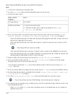
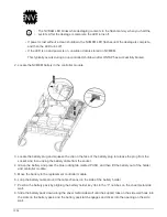
1. Gently remove the bezel from the front of the system.
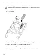
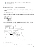
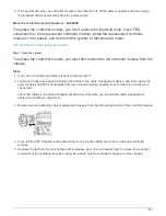
2. Remove the drives:
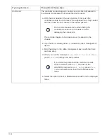
a. Press the release button at the top of the carrier face below the LEDs.
b. Pull the cam handle to its fully open position to unseat the drive from the midplane, and then gently
slide the drive out of the chassis.
The drive should disengage from the chassis, allowing it to slide free of the chassis.
When removing a drive, always use two hands to support its weight.
Drives are fragile. Handle them as little as possible to prevent damage to them.
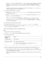
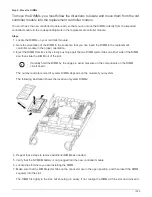
3. Align the drive from the old chassis with the same bay opening in the new chassis.
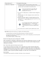
4. Gently push the drive into the chassis as far as it will go.
The cam handle engages and begins to rotate upward.
5. Firmly push the drive the rest of the way into the chassis, and then lock the cam handle by pushing it up
and against the drive holder.
Be sure to close the cam handle slowly so that it aligns correctly with the front of the drive carrier. It click
when it is secure.
6. Repeat the process for the remaining drives in the system.
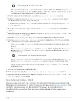
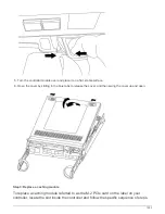
Step 4: Replace a chassis from within the equipment rack or system cabinet
Remove the existing chassis from the equipment rack or system cabinet before you can
install the replacement chassis.
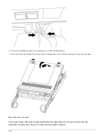
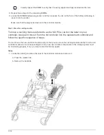
1. Remove the screws from the chassis mount points.
2. With the help of two or three people, slide the old chassis off the rack rails in a system cabinet or
L
brackets in an equipment rack, and then set it aside.
3. If you are not already grounded, properly ground yourself.
4. Using two or three people, install the replacement chassis into the equipment rack or system cabinet by
guiding the chassis onto the rack rails in a system cabinet or
L
brackets in an equipment rack.
5. Slide the chassis all the way into the equipment rack or system cabinet.
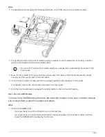
6. Secure the front of the chassis to the equipment rack or system cabinet, using the screws you removed
from the old chassis.
7. If you have not already done so, install the bezel.
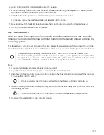
Step 5: Install the controller
After you install the controller module and any other components into the new chassis,
boot it to a state where you can run the interconnect diagnostic test.
For HA pairs with two controller modules in the same chassis, the sequence in which you install the controller
1044
Summary of Contents for AFF A700
Page 4: ...AFF and FAS System Documentation 1...
Page 208: ...3 Close the controller module cover and tighten the thumbscrew 205...
Page 248: ...2 Close the controller module cover and tighten the thumbscrew 245...
Page 308: ...Power supply Cam handle release latch Power and Fault LEDs Cam handle 305...
Page 381: ...Power supply Cam handle release latch Power and Fault LEDs Cam handle 378...
Page 437: ...1 Locate the DIMMs on your controller module 434...
Page 605: ...602...
Page 1117: ...3 Close the controller module cover and tighten the thumbscrew 1114...
Page 1157: ...2 Close the controller module cover and tighten the thumbscrew 1154...
Page 1228: ...Power supply Cam handle release latch Power and Fault LEDs Cam handle 1225...
Page 1300: ...Power supply Cam handle release latch Power and Fault LEDs Cam handle 1297...
Page 1462: ...Installing SuperRail to round hole four post rack 1459...
Page 1602: ...1599...
Page 1630: ...1627...
Page 1634: ...Orange ring on horizontal bracket Cable chain 1631...
Page 1645: ...Guide rail 1642...
Page 1669: ...Attention LED light on 1666...


