
If you miss the prompt and the controller modules boot to ONTAP, enter
halt
, and then
at the LOADER prompt enter
boot_ontap
, press
Ctrl-C
when prompted, and then
repeat this step.
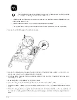
b. From the boot menu, select the option for Maintenance mode.
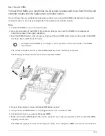
Restoring and verifying the configuration - FAS2600
Step 1: Verify and set the HA state of the chassis
You must verify the HA state of the chassis, and, if necessary, update the state to match
your system configuration.
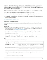
1. In Maintenance mode, from either controller module, display the HA state of the local controller module and
chassis:
ha-config show
The HA state should be the same for all components.
2. If the displayed system state for the chassis does not match your system configuration:
a. Set the HA state for the chassis:
ha-config modify chassis
HA-state
The value for HA-state can be one of the following:
▪
ha
▪
non-ha
b. Confirm that the setting has changed:
ha-config show
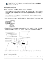
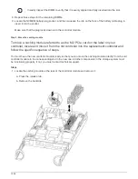
3. If you have not already done so, recable the rest of your system.
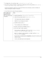
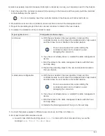
4. The next step depends on your system configuration.
If your system is in…
Then…
A stand-alone configuration
a. Exit Maintenance mode:
halt
b. Go to
"Completing the replacement process
.
An HA pair with a second
controller module
Exit Maintenance mode:
halt
The LOADER prompt appears.
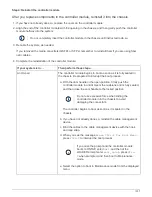
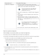
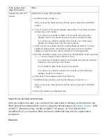
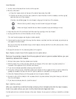
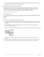
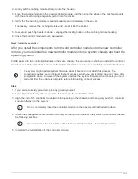
Step 2: Run system-level diagnostics
After installing a new chassis, you should run interconnect diagnostics.
Your system must be at the LOADER prompt to start System Level Diagnostics.
All commands in the diagnostic procedures are issued from the node where the component is being replaced.
1. If the node to be serviced is not at the LOADER prompt, perform the following steps:
1046
Summary of Contents for AFF A700
Page 4: ...AFF and FAS System Documentation 1...
Page 208: ...3 Close the controller module cover and tighten the thumbscrew 205...
Page 248: ...2 Close the controller module cover and tighten the thumbscrew 245...
Page 308: ...Power supply Cam handle release latch Power and Fault LEDs Cam handle 305...
Page 381: ...Power supply Cam handle release latch Power and Fault LEDs Cam handle 378...
Page 437: ...1 Locate the DIMMs on your controller module 434...
Page 605: ...602...
Page 1117: ...3 Close the controller module cover and tighten the thumbscrew 1114...
Page 1157: ...2 Close the controller module cover and tighten the thumbscrew 1154...
Page 1228: ...Power supply Cam handle release latch Power and Fault LEDs Cam handle 1225...
Page 1300: ...Power supply Cam handle release latch Power and Fault LEDs Cam handle 1297...
Page 1462: ...Installing SuperRail to round hole four post rack 1459...
Page 1602: ...1599...
Page 1630: ...1627...
Page 1634: ...Orange ring on horizontal bracket Cable chain 1631...
Page 1645: ...Guide rail 1642...
Page 1669: ...Attention LED light on 1666...